Solid source precursor vessel

a precursor vessel and solid source technology, applied in the direction of chemical vapor deposition coating, coating, metal material coating process, etc., can solve the problem of long interval between replacement and/or refilling achieve the effect of increasing the capacity of the source vessel, increasing density, and prolonging intervals

Pending Publication Date: 2021-11-04
ASM IP HLDG BV
View PDF6 Cites 0 Cited by
  • Summary
  • Abstract
  • Description
  • Claims
  • Application Information

AI Technical Summary

Benefits of technology

[0009]The present disclosure is generally directed to a solid source precursor delivery system. More specifically, the present disclosure is directed to a solid source precursor vessel that is utilized to vaporize a supply of solid precursor stored within the vessel. The disclosed source vessel replaces a single serpentine channel used to store a supply of precursor and direct a carrier gas through the vessel with a plurality of individual cavities or pockets within the interior of the vessel. Each individual pocket may be loaded with precursor. In an arrangement, the pockets may be loaded with pre-formed blocks of compressed precursor that typically have a higher density than may be achieved when packing a powdered precursor in a serpentine channel. The increased density of the solid precursor material increases a capacity of the source vessel, resulting in longer intervals between replacement and / or refilling the source vessel.
[0010]In an arrangement, a reactant source vessel is provided that includes a container body and a lid. The lid is configured to attach to the container body to enclose an internal area of the container body defined by one or more sidewalls and a bottom surface. Formed within the internal area of the container body are a plurality of individual pockets that are each configured to hold a volume of solid source precursor. In an arrangement, the pockets may be of a uniform size (e.g., have common dimensions). The individual pockets may have any configuration. For instance, the pockets may be cylindrical, rectangular prismatic, etc. Generally, each pocket has a closed lower or bottom end, one or more sidewalls and an open upper end. In such an arrangement, the pockets may receive a preformed block of compressed solid precursor (e.g., through the open upper end). This arrangement facilitates loading the source vessel. The plurality of individual pockets within the interior of the source vessel are each exposed to a fluid flow path passing through the interior of the vessel between a fluid path inlet end and a fluid path outlet end. This fluid path passes over each individual pocket within the source vessel to permit carrying vaporized precursor from the source vessel. In order to route the fluid path over the open end of each pocket, the path may be non-direct (e.g., serpentine) between the fluid path inlet end and the fluid path outlet end.
[0011]In an arrangement, the container body has a two-piece construction. In this arrangement, the container body may have a base that receives an insert in which the plurality of pockets are formed. In a further arrangement, the insert may be formed in multiple layers that are stacked to form the plurality of pockets. Such an arrangement may be beneficial when working with hard and / or brittle material.
[0012]In another arrangement, the plurality of pocket may be formed by a plurality of intersecting dividing walls that that collectively define a matrix of pockets within the interior of the container body. In an arrangement, the dividing walls may be evenly spaced to enhance heat transfer throughout the container body. In such an arrangement, the container body may have a high degree of symmetry.

Problems solved by technology

The increased density of the solid precursor material increases a capacity of the source vessel, resulting in longer intervals between replacement and / or refilling the source vessel.

Method used


Image

  • Solid source precursor vessel
  • Solid source precursor vessel
  • Solid source precursor vessel

Examples


Embodiment Construction

[0024]The description of exemplary embodiments provided below is merely exemplary and is intended for purposes of illustration only; the following description is not intended to limit the scope of the disclosure or the claims. Moreover, recitation of multiple embodiments having stated features is not intended to exclude other embodiments having additional features or other embodiments incorporating different combinations of the stated features.

[0025]The present disclosure generally relates to improved solid source precursor vessels, apparatuses and methods. The disclosed embodiments allow for providing ready access to reactant vapor while providing improved serviceability (e.g., recharging) of the solid source precursor vessel.

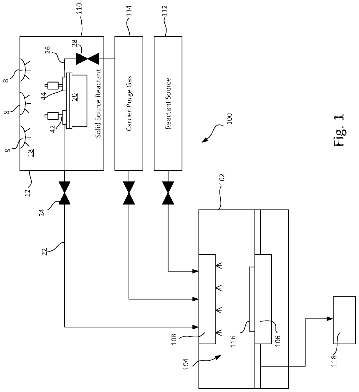
[0026]FIG. 1 schematically illustrates an exemplary gas-phase reactor system 100, which includes a reactor 102, including a reaction chamber 104, a susceptor 106 to hold a substrate 116 during processing, a gas distribution system 108 to distribute one or more...


PUM

PropertyMeasurementUnit
densityaaaaaaaaaa
densityaaaaaaaaaa
internal areaaaaaaaaaaa

Abstract

The present disclosure is generally directed to a solid source precursor delivery system. More specifically, the present disclosure is directed to a solid source precursor vessel that can be utilized to vaporize a supply of solid precursor stored within the vessel. The disclosed source vessel utilizes a plurality of individual cavities or pockets within the interior of the vessel. Each individual pocket may be loaded with precursor. In an arrangement, the pockets may be loaded with pre-formed blocks of compressed precursor material that typically have a higher density than was previously achieved when packing solid precursor within a source vessel. The increased density of the solid precursor material increases a capacity of the source vessel resulting in longer intervals between replacement and / or refilling the source vessel.

Description

CROSS-REFERENCE TO RELATED APPLICATIONS[0001]This application is a Nonprovisional of, and claims priority to and the benefit of, U.S. Provisional Patent Application No. 63 / 017,279, filed Apr. 29, 2020 and entitled “SOLID SOURCE PRECURSOR VESSEL,” which is hereby incorporated by reference herein.FIELD OF THE DISCLOSURE[0002]The present disclosure generally relates to gas-phase reactors and systems. More particularly, the disclosure relates to an apparatus for delivering reactant gases from solid source precursors.BACKGROUND OF THE DISCLOSURE[0003]Gas-phase reactor systems, such as chemical vapor deposition (CVD), plasma-enhanced CVD (PECVD), and atomic layer deposition (ALD) can be used for a variety of applications, including depositing and etching materials on a substrate surface (e.g., semiconductor wafer). For example, gas-phase reactor systems can be used to deposit and / or etch layers on a substrate to form semiconductor devices, flat panel display devices, photovoltaic devices,...

Claims


Application Information

Patent Timeline
Patent Type & Authority Applications(United States)
IPC IPC(8): C23C16/448C23C16/44C23C16/455C23C16/50
CPCC23C16/448C23C16/50C23C16/45525C23C16/4408C23C16/54C23C16/45544C23C16/455C23C16/4485C23C16/45561C23C16/4481C23C16/44
Inventor HUANG, JIANQIUKIMTEE, ANKITBIYANI, SUDHANSHUBAKKE, JONATHAN ROBERTSHERO, ERIC JAMES
Owner ASM IP HLDG BV
Why Eureka
Try Eureka