Concrete-Filled Steel Tubular Column-Steel Plate Concrete Ring Beam Joint and Construction Method Thereof

a technology of concrete ring beam joints and steel tubular columns, which is applied in the direction of construction, building construction, etc., can solve the problems of increasing the difficulty of manufacturing, construction and installation, increasing the cost of joints, and not being very reasonable, and achieves low cost, simple structure, and reliable transfer of bending moment and shear force

Active Publication Date: 2021-11-04
SOUTH CHINA UNIV OF TECH
View PDF0 Cites 2 Cited by
  • Summary
  • Abstract
  • Description
  • Claims
  • Application Information

AI Technical Summary

Benefits of technology

[0003]In view of the technical problems existing in the prior art, an object of the present invention is: to provide a concrete-filled steel tubular column-steel plate concrete ring beam joint. A steel plate construction is added to the ring beam joint to ensure the seismic performance of the connection joint, and the section width of the steel plate concrete ring beam can be significantly reduced.
[0004]Another object of the present invention is to provide a construction method of a concrete-filled steel tubular column-steel plate concrete ring beam joint. The construction method is simple and can reduce the amount of on-site workload for the joint and improve the level of industrial construction.

Problems solved by technology

However, there are still some technical problems that can be improved in the concrete-filled steel tubular column-concrete ring beam connection joint itself or its application in engineering practices.
Wide and thick concrete ring beams affect the use of a building space, with limitations in the use of edge joints and partial door and window opening positions of the frame structure, the difficulty in manufacturing, construction and installation is thus increased, and the cost of joints is directly increased.
In addition, the concrete ring beam is usually designed in a symmetrical form centered on the concrete-filled steel tubular column; however, for a large eccentric joint (such as a corner column and a side column) where the frame beam connected to the concrete ring beam is biased towards one side, there is a limitation in the application of the centrosymmetric concrete ring beam, the stress is not very reasonable and the other side without the beam is too wasteful.

Method used


Image

  • Concrete-Filled Steel Tubular Column-Steel Plate Concrete Ring Beam Joint and Construction Method Thereof
  • Concrete-Filled Steel Tubular Column-Steel Plate Concrete Ring Beam Joint and Construction Method Thereof
  • Concrete-Filled Steel Tubular Column-Steel Plate Concrete Ring Beam Joint and Construction Method Thereof

Examples


embodiment 1

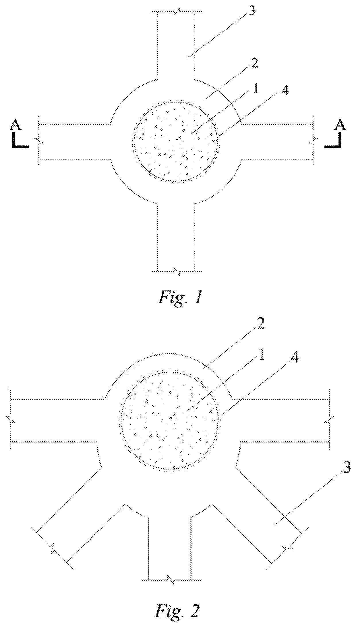
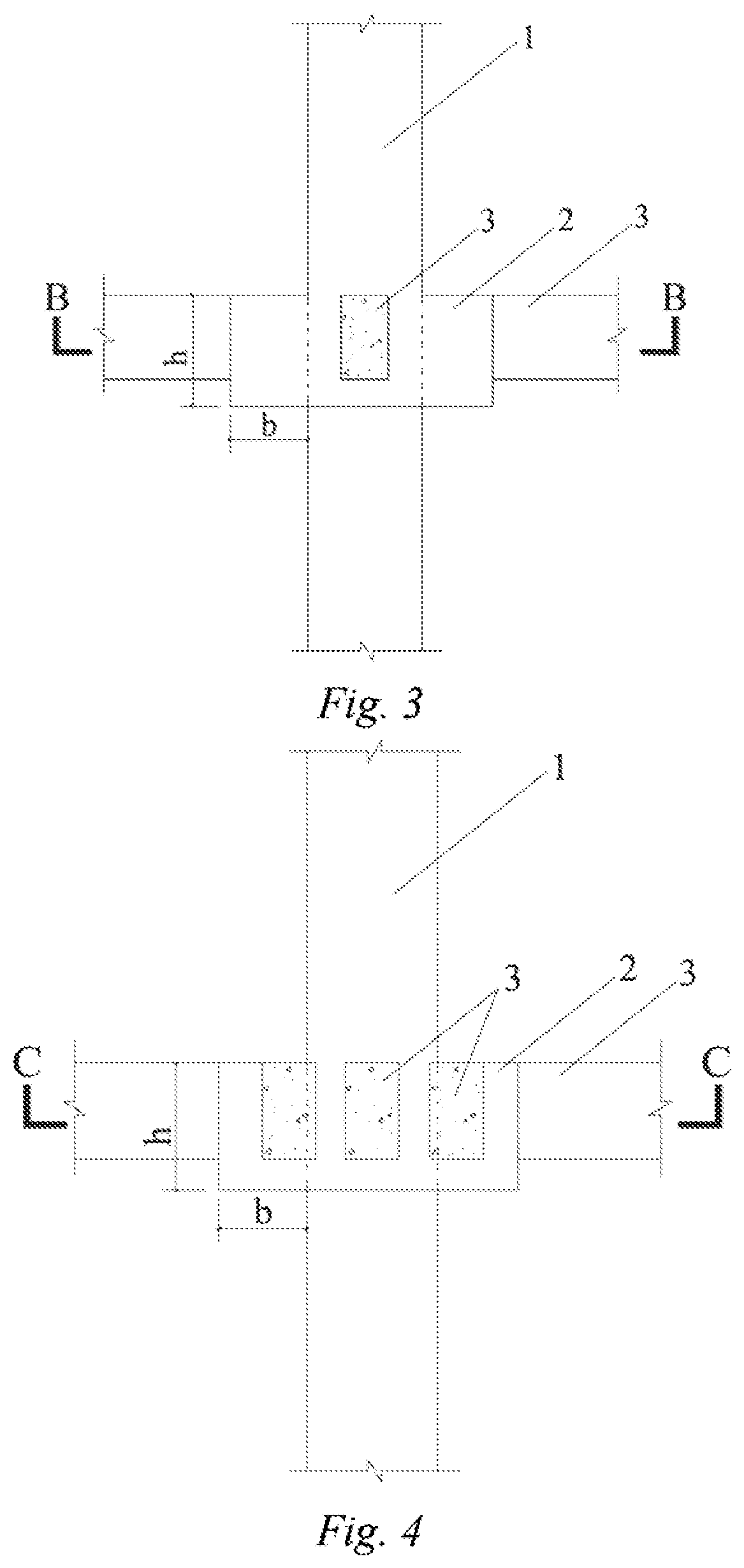
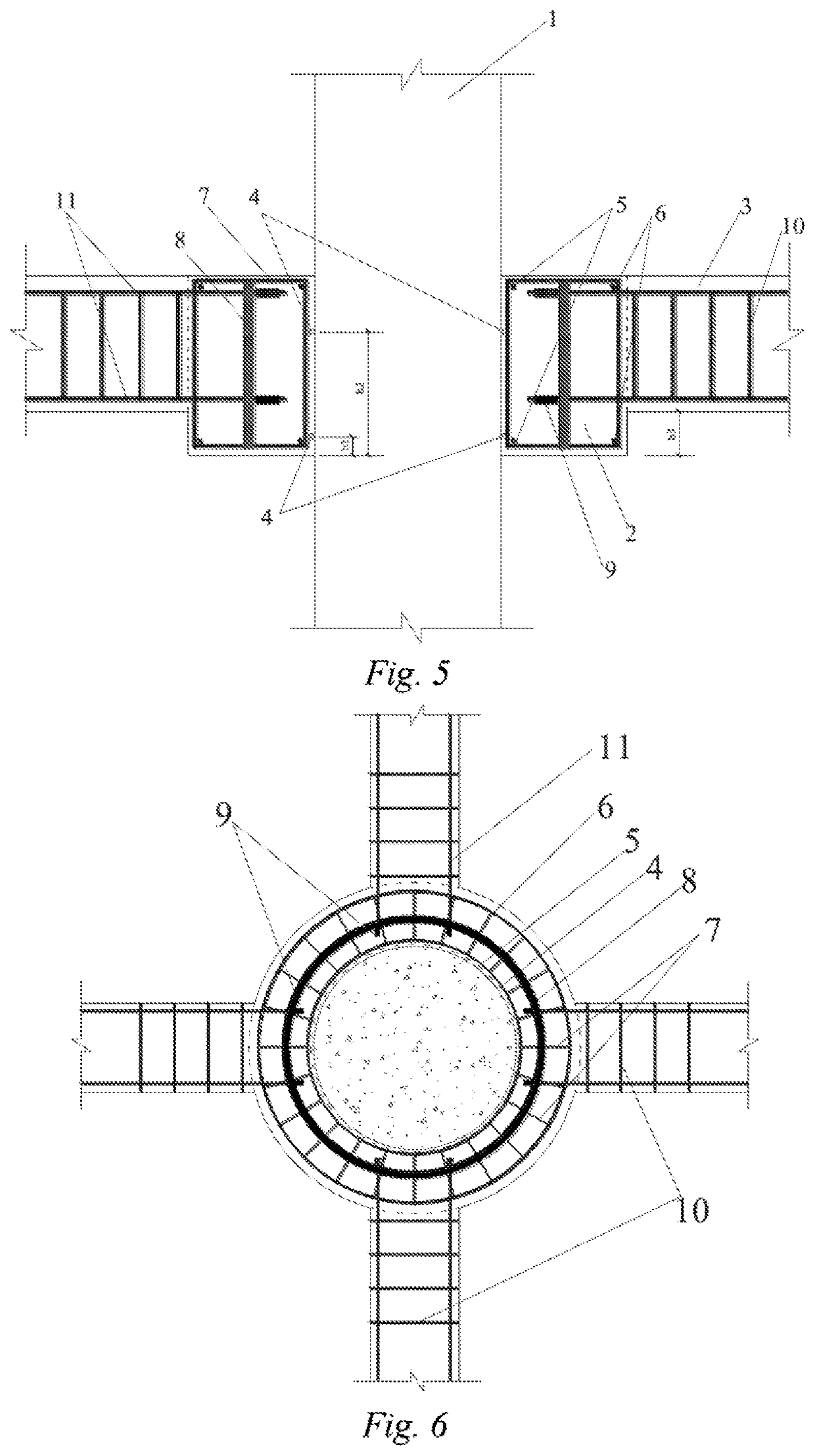
[0035]A concrete-filled steel tubular column-steel plate concrete ring beam joint comprises: a concrete-filled steel tubular column, a steel plate concrete ring beam of a centrosym metric ring shape, reinforced concrete frame beams, and shear ring reinforcements. The steel plate concrete ring beam comprises: an I-shaped steel plate, a reinforcing cage, and concrete. The steel plate is preset with holes through which the stressed reinforcement of the reinforced concrete frame beam passes and concrete grouting holes which are convenient for concrete to flow on both sides of the steel plate. As shown in FIG. 5 and FIG. 6, the shear ring reinforcements are pasted and welded to the upper and lower parts within the height of the steel plate concrete ring beam on the outer side wall of the concrete-filled steel tubular column. Shear ring reinforcements are used to inhibit the bond-slip between the steel plate concrete ring beam and the outer wall of the concrete-filled steel tubular column...

embodiment 2

[0046]The steel plate concrete ring beam is of an eccentric ring shape, and a steel plate and a reinforcing cage each are of an eccentric ring shape. The steel plate-reinforcing cage is prefabricated. The steel plate concrete ring beam of an eccentric ring shape is more applicable for the large eccentric joint where the frame beam connected to the steel plate concrete ring beam is biased towards one side, and the stress is reasonable.

[0047]The parts not mentioned in this embodiment are the same as those in embodiment 1, and will not be described here again.


PUM


Abstract

The present invention relates to a concrete-filled steel tubular column-steel plate concrete ring beam joint, comprising: a concrete-filled steel tubular column, a steel plate concrete ring beam and reinforced concrete frame beams. The steel plate concrete ring beam comprises: a steel plate and a reinforcing cage, wherein concrete grouting holes are arranged in the middle of the steel plate; both the steel plate and the reinforcing cage are of a ring shape, and the ring-shaped steel plate and the reinforcing cage are coaxially arranged; the steel plate concrete ring beam is sheathed and fixed on the outer side wall of the concrete-filled steel tubular column; and an end of the reinforced concrete frame beam extends into the steel plate concrete ring beam, and stressed reinforcements of the reinforced concrete frame beam are connected to the steel plates. The steel plate concrete ring beam is of a centrosymmetric ring-shaped or eccentric ring-shaped construction. The stressed reinforcement of the reinforced concrete frame beam is anchored by the ring beam joint through the steel plates, so that the seismic performance of the connection joint is ensured, the section width of the steel plate concrete ring beam can be significantly reduced, and the spatial applicability of the joint is improved. The present invention also relates to a construction method of a concrete-filled steel tubular column-steel plate concrete ring beam joint, belonging to the field of building structures.

Description

TECHNICAL FIELD[0001]The present invention relates to the field of building structures, and in particular to a concrete-filled steel tubular column-steel plate concrete ring beam joint and construction method thereof.BACKGROUND ART[0002]Concrete-filled steel tubular members are internationally recognized structural carrying elements with higher structural efficiency and stronger spanning capacity, complying with the current development trend of green and energy-saving industries. The connection technology of a concrete-filled steel tubular column-reinforced concrete frame beam is one of the key technologies to ensure the overall robustness, seismic performance and construction efficiency of a concrete-filled steel tubular frame structure. However, there are still some technical problems that can be improved in the concrete-filled steel tubular column-concrete ring beam connection joint itself or its application in engineering practices. Although the concrete-filled steel tubular col...

Claims


Application Information

Patent Timeline
Patent Type & Authority Applications(United States)
IPC IPC(8): E04B1/18E04B1/30
CPCE04B1/185E04B1/30E04B1/24E04B2001/2478E04B1/215
Inventor ZHOU, JINGFANG, XIAODAN
Owner SOUTH CHINA UNIV OF TECH
Why Eureka
Try Eureka