
Chopper system and method

a chopper and frequency technology, applied in the field of systems, can solve the problems of additional implementation outlay, undesirable stabilization or overshooting behavior, and additional delay times,

Pending Publication Date: 2021-11-04
INFINEON TECH AG
View PDF9 Cites 0 Cited by
  • Summary
  • Abstract
  • Description
  • Claims
  • Application Information

AI Technical Summary

Benefits of technology

The patent describes a way to reduce ripples and offsets caused by a variable chopper frequency in a chopper demodulator. This is accomplished by using a feedback path from the output of the chopper demodulator to the chopped apparatus. The technical effect of this innovation is improved performance and accuracy in measuring and controlling the chopping process.

Problems solved by technology

However, chopping produces a ripple at the chopper frequency.
To eliminate these ripples, conventional approaches use a lowpass filter or notch filter, which can mean additional implementation outlay, additional delay times and undesirable stabilization or overshoot behavior.
Such a filter can moreover result in interference signals at multiples of the chopper frequency.
This can occur in the event of undesirable interference injection at the output of a chopper arrangement and can lead to undesirable demodulation effects that can distort the useful signal in the DC component or in the useful frequency range, in particular in the case of systems with radio-frequency interference from the surroundings of the system.
However, this has the disadvantage that offset components are not completely up-modulated to a fixed chopper frequency and cannot subsequently be selectively filtered out, but rather mixed frequencies lead to aliasing (down-demodulation), which can manifest itself as an increase in noise in the useful signal.

Method used


Image

  • Chopper system and method
  • Chopper system and method
  • Chopper system and method

Examples


example 5

[0075] System according to one of examples 1 to 4, wherein the feedback path has a filter frequency that is lower than a minimum chopper frequency of the variable chopper frequency by at least a factor of 2.

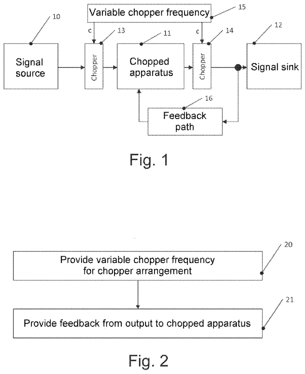
[0076]Example 6. System according to one of examples 1 to 5, wherein the feedback path comprises a demodulator, which is configured to operate based on the chopper signal, and an integrator.

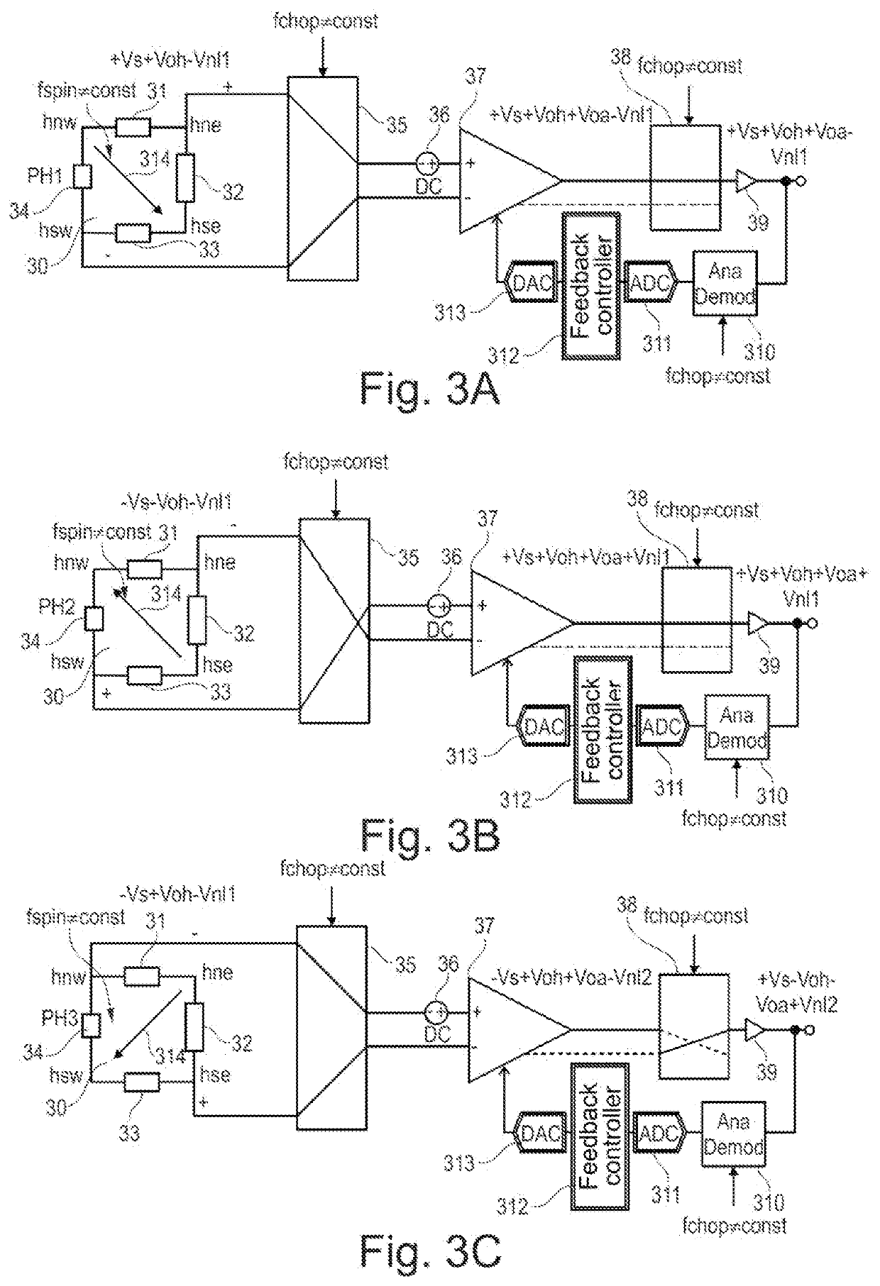
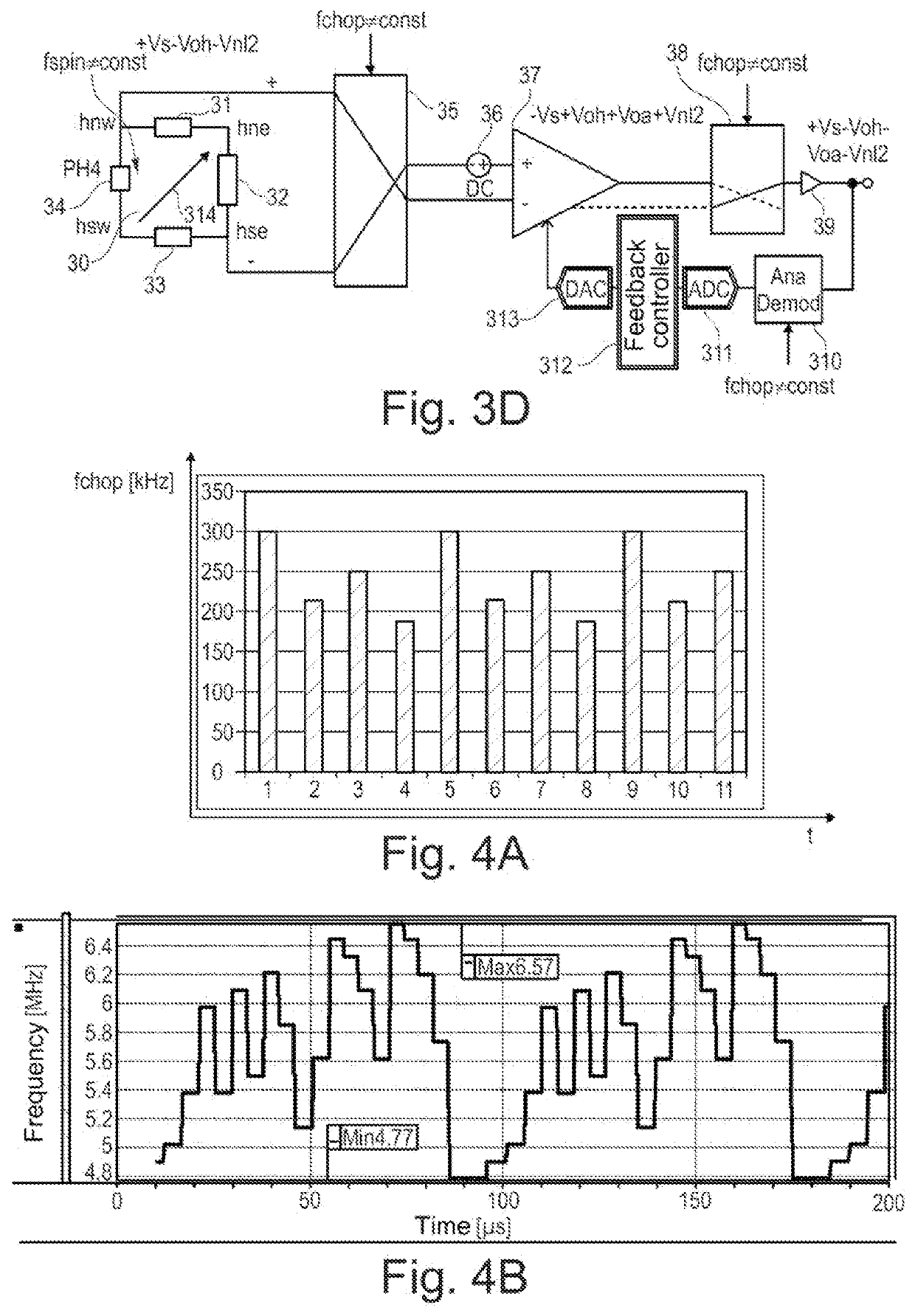
[0077]Example 7. System according to one of examples 1 to 6, moreover comprising a spinning current Hall sensor, wherein an output of the spinning current Hall sensor is coupled to an input of the chopper modulator, wherein the spinning current Hall sensor is configured to be operated at a variable spinning frequency that is an integer multiple of the variable chopper frequency.

[0078]Example 8. Method, comprising:

[0079]providing a chopper signal having a variable chopper frequency to a chopper arrangement, and

[0080]providing feedback from an output of the chopper arrangement to a chopped appar...

example 13

[0086] Method according to one of examples 8 to 12, wherein the providing of the feedback comprises demodulating an output signal of the chopper arrangement based on the chopper signal, and integrating the demodulated output signal.

[0087]Example 14. Method according to one of examples 8 to 13, moreover comprising operating a Hall sensor using a spinning current technique, wherein an output of the Hall sensor is coupled to an input of the chopper arrangement, wherein the spinning current technique is operated at a variable spinning frequency that is an integer multiple of the variable chopper frequency.


PUM


Abstract

Systems and methods are provided for which a chopper modulator and a chopper demodulator of a chopped apparatus having a variable chopper frequency are described. A feedback path is used to reduce ripples and / or remaining offsets as a result of the variable chopper frequency.

Description

CROSS REFERENCE TO RELATED APPLICATION[0001]This application claims priority to German Patent Application No. 102020111914.3, filed on May 4, 2020, the contents of which are incorporated by reference herein in their entirety.TECHNICAL FIELD[0002]The present application concerns systems that employ chopping, and corresponding methods.BACKGROUND[0003]Chopping is a technique that involves an input signal and an output signal of an apparatus each being modulated with a chopper signal that has a chopper frequency. The apparatus can be an analog-to-digital converter or an amplifier, for example, and is referred to generally as a chopped apparatus in this application. By way of example, such a chopper signal can alternately assume values of +1 and −1 at a chopper frequency, and the input signal and the output signal of the chopped apparatus are multiplied by this signal for the purpose of modulation.[0004]This chopping eliminates a DC voltage offset of the chopped apparatus or at least dec...

Claims


Application Information

Patent Timeline
Patent Type & Authority Applications(United States)
IPC IPC(8): H03F3/38G01R33/07
CPCH03F3/38H03F2200/459G01R33/075H03M1/04H03M1/0626H03F1/26H03F3/45H03F3/387H03F3/45475H03F2200/261G01R33/0023
Inventor MOTZ, MARIOARACRI, UMBERTO
Owner INFINEON TECH AG
Learn More