
Glass tube

Pending Publication Date: 2021-11-11
SCHOTT AG
View PDF0 Cites 0 Cited by
  • Summary
  • Abstract
  • Description
  • Claims
  • Application Information

AI Technical Summary

Benefits of technology

The patent describes a process for producing glass tubes using a rotating conical mandrel. Molten glass is applied to the outer surface of the mandrel and formed into a hollow body, which is then drawn from the mandrel in a certain direction to form the glass tube. The spatial variation of the wetting zone of the applied glass melt is continuously monitored and adjusted by adjusting process parameters. The resulting glass tubes have a consistent quality and can be used in various applications.

Problems solved by technology

Particularly, hot forming processes for making pharmaceutical containers from glass tubes tend to be difficult to run stably, because a vast number of parameters needs to be optimized in order to ac-count for variations in quality of the hot-formed product.

Method used


Image

  • Glass tube
  • Glass tube
  • Glass tube

Examples


example 1

[0092]A glass tube 14 of 1.5 m length was prepared using the Danner method described in this disclosure. The glass processed in this manner had the following VFT constants: A=−1.41; B=5047.3; T0=224.7° C.

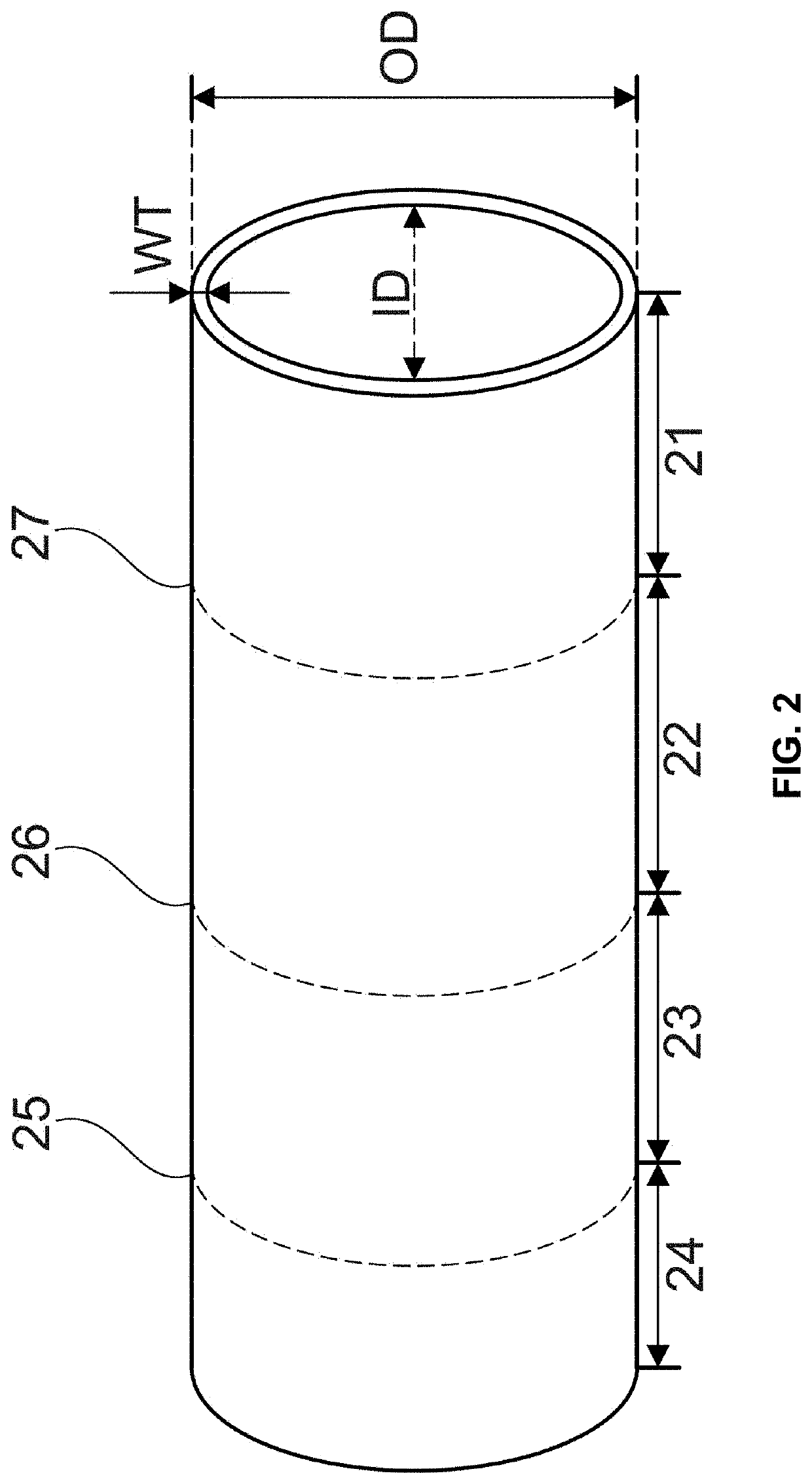
[0093]Three cross-sectional area values along the length of the corresponding glass tube 14 were determined. The first value was determined by measuring the outer diameter and the wall thickness of a first cross-section 25, the second value was determined by measuring the outer diameter and the wall thickness of a second cross-section 26 and the third value was determined by measuring the outer diameter and the wall thickness of a third cross-section 27. The sizes of the three cross-sectional areas were compared to determine which was the largest of the three (QFmax), and which was the smallest (QFmin). Measurements were repeated for three tubes. For Tube 1, the highest cross-sectional area QFmax was measured at the first cross-section 25. The lowest cross-sectional area QFmin was m...

example 2

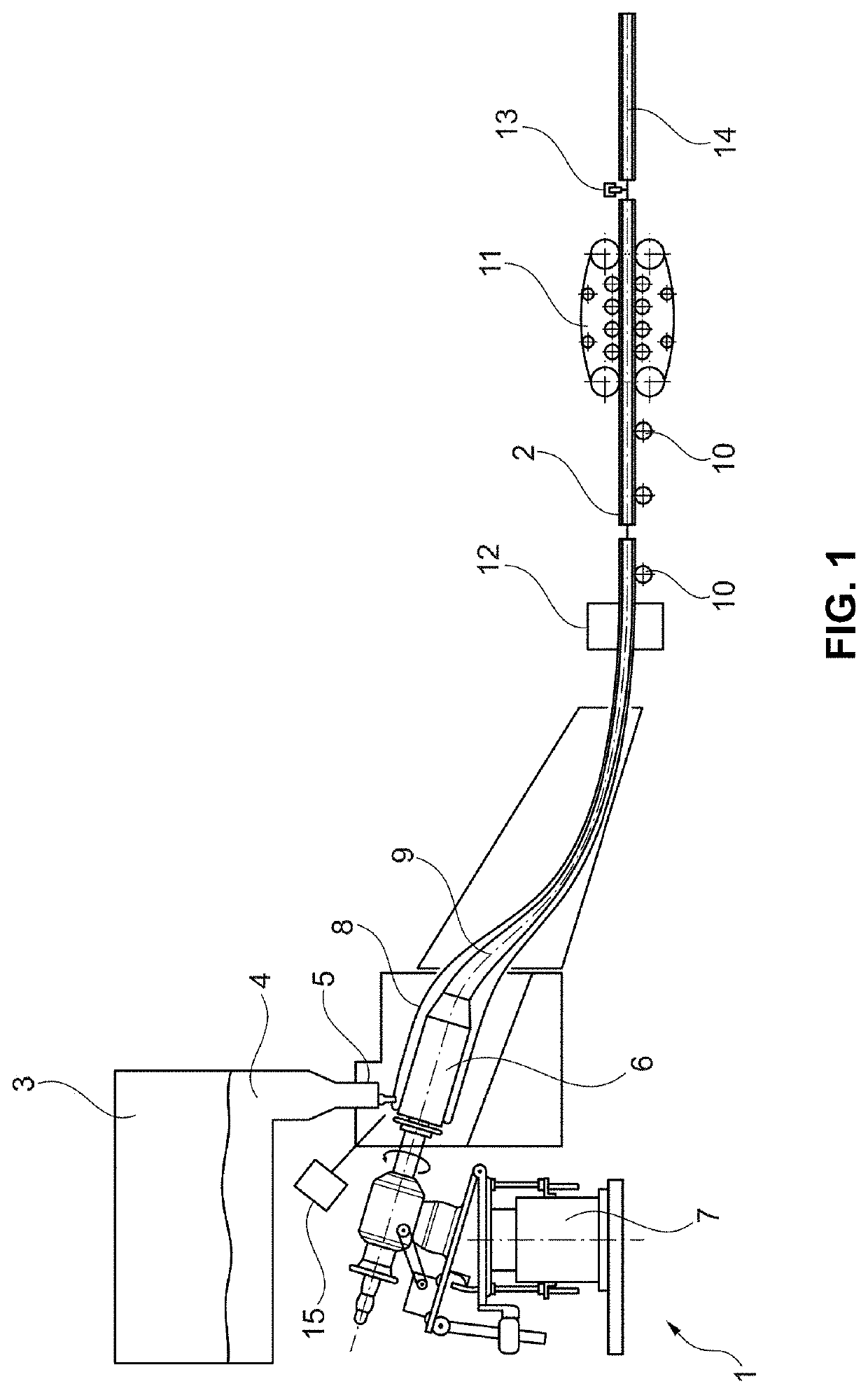
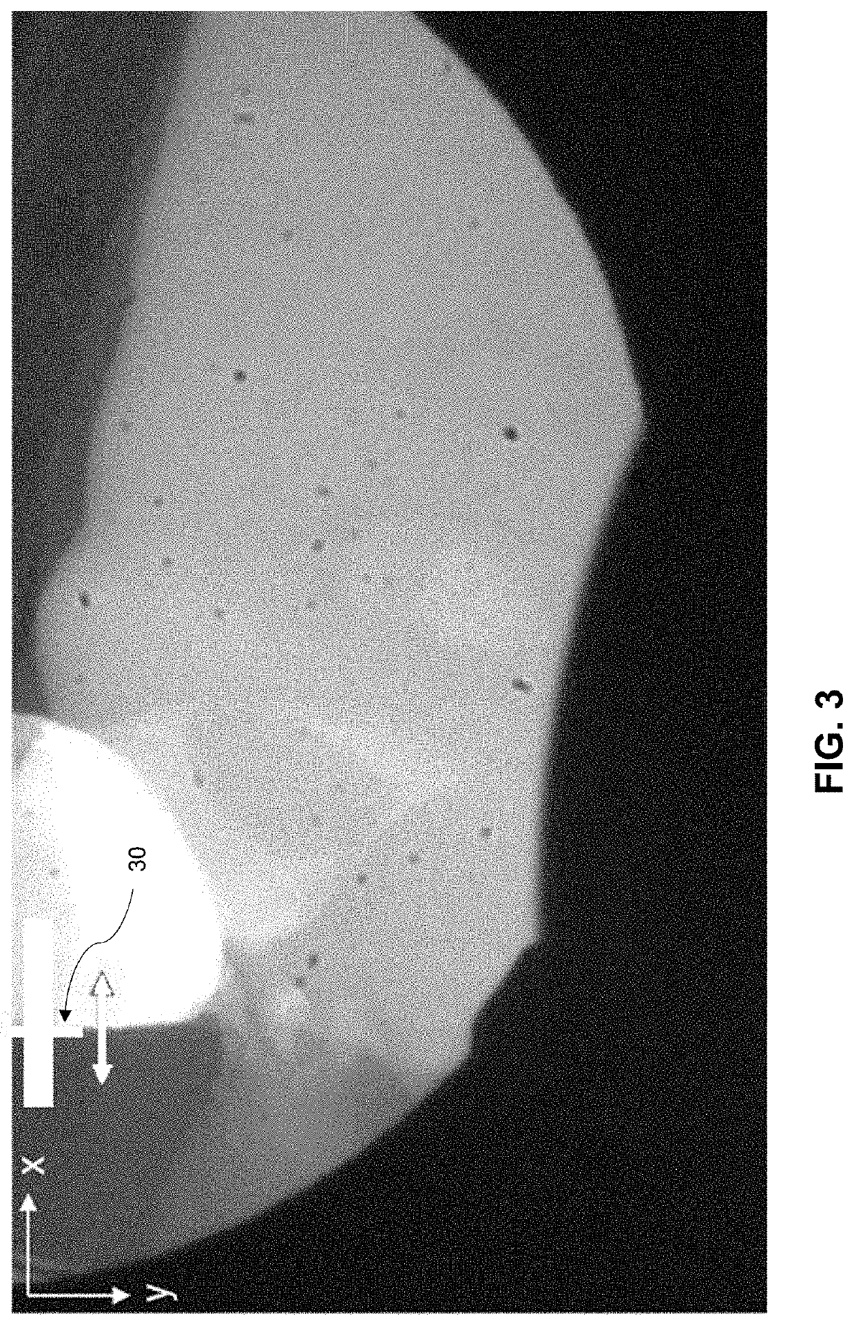
[0094]Glass tubes 14 were produced according to the Danner method. During operation, the spatial variation of the glass strand (FIG. 3) was monitored using a camera 15. The spatial variation is the movement of the edge 30 of the glass strand as the glass flows onto the conical mandrel 6. FIG. 5 shows the distribution of the X-position of the black-white-edge 30 in a first time interval. In this first interval, the rotational speed of the conical mandrel 6 was 9.7 rpm and the spatial variation σ was about 2.35 pixels.

[0095]In a second time interval, the rotational speed was adjusted to reduce the spatial variation σ of the edge 30 of the glass strand. After adjustment, the rotational speed was 10.3 rpm and the spatial variation was reduced to 1.35 pixels.

[0096]The first interval had a broad distribution of locations of the edge of the glass strand, i.e. stronger movement of the glass strand in the wetting zone. The second interval had a narrower distribution. Broad and narrow distrib...


PUM

PropertyMeasurementUnit
Temperatureaaaaaaaaaa
Lengthaaaaaaaaaa

Abstract

A glass tube, such as a glass tube for the production of containers for storage of pharmaceutical compositions, facilitates production of pharmaceutical containers with high quality. The glass tube has a relative cross-sectional area deviation defined asQFmax-QFmin1.5⁢⁢m.QFmax-QFmin1.5⁢⁢mis less than k*x+t. QFmax is the highest cross-sectional area and QFmin is the lowest cross-sectional area of at least two cross-sections of the glass tube, the cross-sections being spaced apart from each other along a length of the glass tube, and k is 0.0023 m−1, t is less than 0.15 mm2 / m and x isQFmax+QFmin2.

Description

CROSS REFERENCE TO RELATED APPLICATIONS[0001]This application claims priority to European Patent Application EP 20173251.8, filed on May 6, 2020, which is incorporated in its entirety herein by reference.BACKGROUND OF THE INVENTION1. Field of the Invention[0002]The present invention relates to a glass tube, in particular a glass tube for the production of containers for storage of pharmaceutical compositions. The glass tube facilitates production of pharmaceutical containers with particularly high quality. Further, the present invention relates to a method for the production of a glass tube.2. Description of the Related Art[0003]For the production of glass tubes, in particular glass tubes for the production of pharmaceutical containers, such as ampoules, vials, cartridges or syringes, the so-called Danner process is often used. In the Danner process, a glass melt emerging out of a melting tank flows onto the outer surface of a rotating tubular body (so-called Danner mandrel) to form...

Claims


Application Information

Patent Timeline
IPC IPC(8): C03B17/04A61J1/06A61J1/14C03C3/091C03C3/087
CPCC03B17/04A61J1/065C03C3/087C03C3/091A61J1/1468C03C3/083C03C3/093C03B19/00C03B15/14
Inventor LENZ, THOMASLANGSDORF, ANDREASETZOLD, FABIANGROSS, CHRISTOPHLANGE, ULRICHOLLIG, MARKUSRIECKE, ARNEWALLAT, WOLFGANG
Owner SCHOTT AG
Learn More