
Method for separating targets and clutter from noise, in radar signals

a radar signal and target technology, applied in the field of moving platform radar systems, can solve problems such as environmental noise, difficult and sometimes impossible maneuvers, and difficulty in directing radar sensors to the sky

Active Publication Date: 2021-11-18
ARBE ROBOTICS LTD
View PDF4 Cites 10 Cited by
  • Summary
  • Abstract
  • Description
  • Claims
  • Application Information

AI Technical Summary

Benefits of technology

The present invention is about a method and system for separating large and small targets from noise in radar signals. The technique involves transmitting chirp-modulated radar signals to targets of different sizes, and then receiving the echo signals reflected from these targets. The echo signals are then down-converted and sampled to obtain an intermediate frequency (IF) signal. The received IF signal is processed to obtain power spectral components associated with the targets and irrelevant frequency domain. The noise levels in the relevant frequency domain are calculated, and then targets are detected by comparing the power spectral components to the calculated noise levels. The invention has the advantage of accurately separating targets and clather from noise in radar signals.

Problems solved by technology

The first source is environmental noise, which is temperature dependent.
However, directing the radar sensor to the sky is problematic and requires difficult and sometimes impossible maneuvers, which should be done periodically, in order to calibrate the noise level.
However, all conventional radar-based sensing systems have not provided satisfactory solutions to the problem of evaluating the noise power, when the detected targets are large and not point targets and / or containing large number of dense targets.

Method used


Image

  • Method for separating targets and clutter from noise, in radar signals
  • Method for separating targets and clutter from noise, in radar signals
  • Method for separating targets and clutter from noise, in radar signals

Examples


example 1

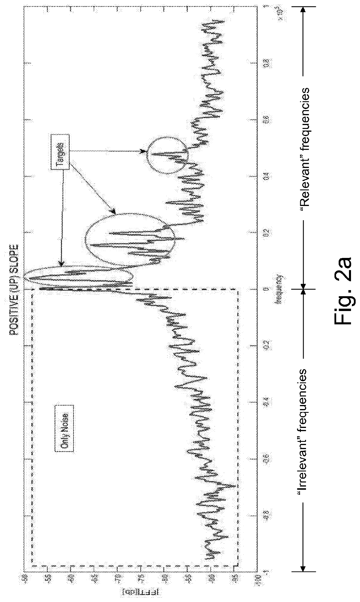
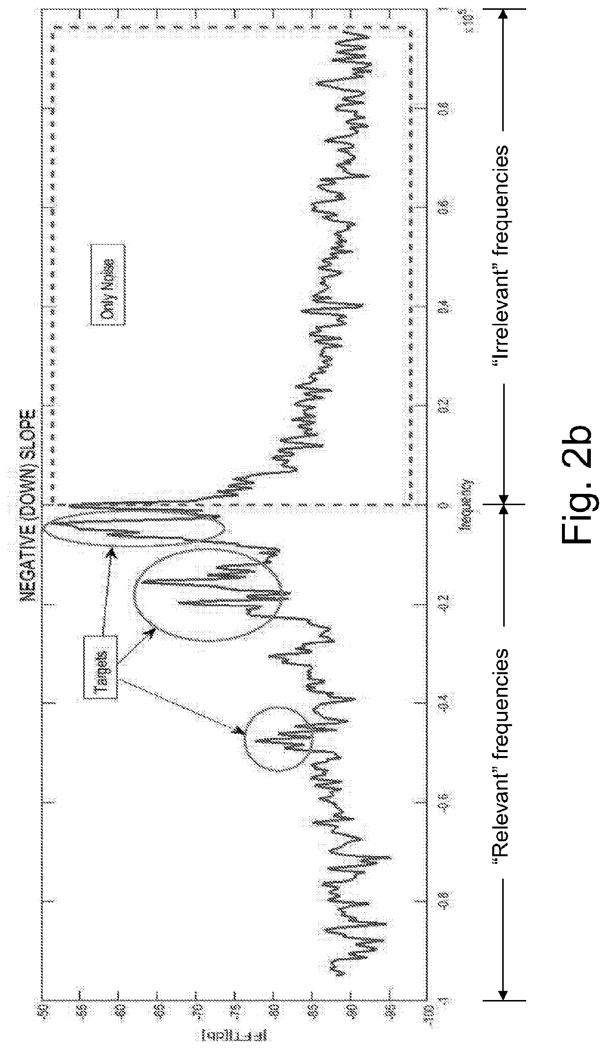
[0044]For each recorded fIF of one sweep, calculate the furrier transform of the signal (FFT). For each “relevant” frequency (f), find the max amplitude value of a window of size N (N can be, but not limited to 20 frequency bins) around the corresponding “irrelevant” frequency (−f). Then, the signal power at each relevant frequency is compared with the computed noise level described above.

example 2

[0045]Use signal data of M sweeps, M can be equal but not limited to 100. For each frequency f, the variance (σ2) of the Rayleigh distribution (a continuous probability distribution for positive-valued random variables) is calculated from the PDF (Probability Density Function) of the M amplitudes from the “irrelevant” frequency −f. The variance σ2 is used to calculate the probability that the amplitude of the frequency f is the result of only noise.

[0046]Both examples are based on methods used to conclude the probability that the signal came from noise and recognize that the distribution of the amplitude in the ‘irrelevant’ frequencies came from the same random variable as the noise in the ‘relevant’ frequencies.

[0047]Using those methods, every target, regardless of its size will be detected reliably and not only parts of it (as prior art methods do), since a large target will be described by a set of consequent relevant frequencies. For example, if a target is a 10 meters long side...


PUM


Abstract

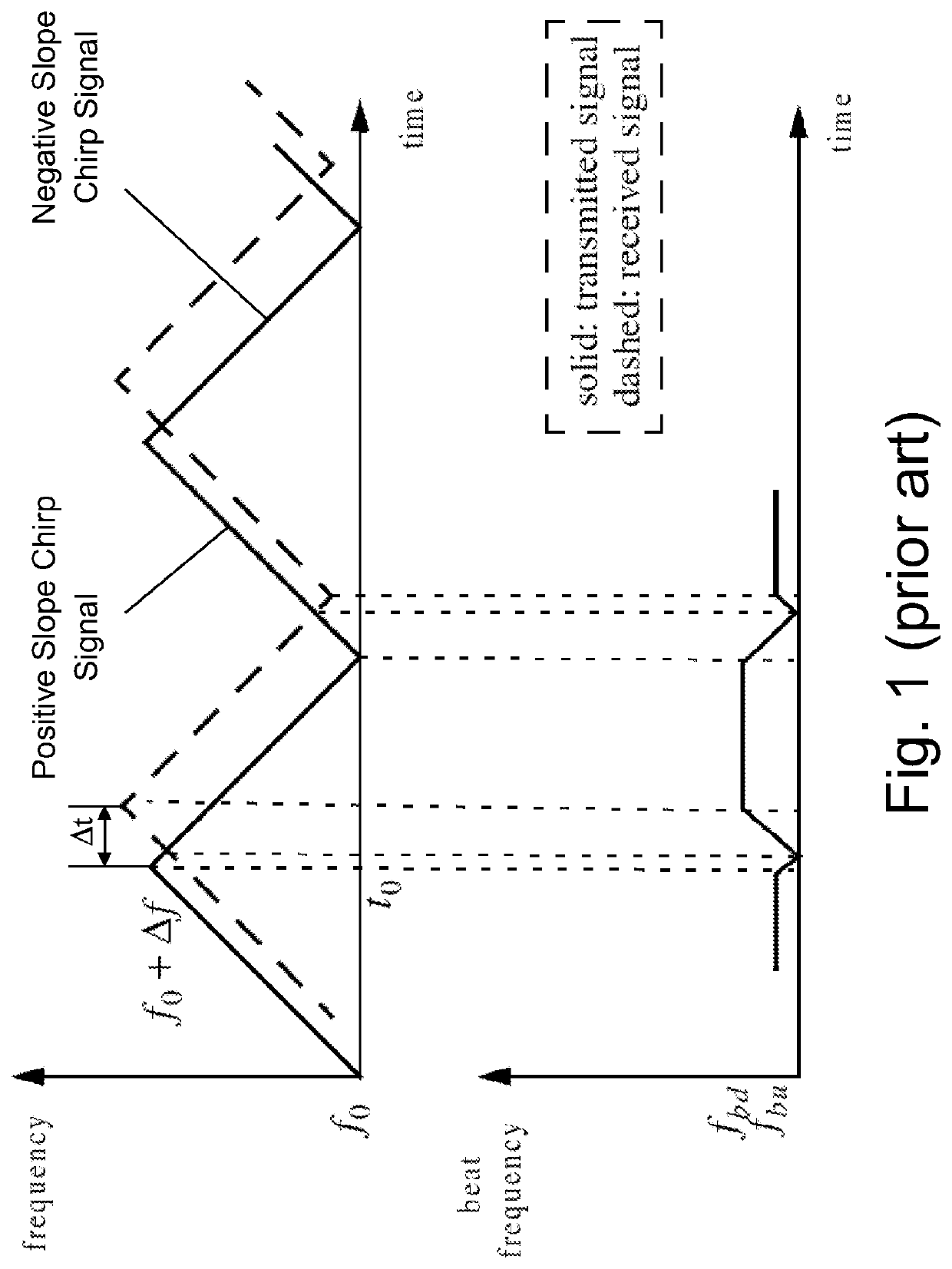
A method for separating large and small targets from noise in radar IF signals, according to which a receiver receives, echo signals that are reflected from targets of different size (such as walls or ground), in response to the transmission of chirp FMCW radar signals, modulated (e.g., using Linear Frequency Modulation) in a predetermined modulation speed for a predetermined duration. The echo signals are down-converted by mixing them with the transmitted signal, to obtain received Intermediate Frequency (IF) signal, which is then sampled both in phase (I-channel) and in quadrature phase (Q-channel). The received IF signal passes a Fourier transform, to obtain power spectral components that belong to a relevant frequency domain, associated with an echo signal reflected from a real target, along with corresponding power spectral components that belong to an irrelevant, opposite frequency domain. The noise distribution and level in the relevant frequency domain is calculated by estimating the noise level in the irrelevant frequency domain and targets represented by a set of consequent relevant frequencies are detected by comparing the power spectral component at each relevant frequency to the calculated noise level and identifying power spectral components with likelihood, which is above a predetermined threshold.

Description

FIELD OF THE INVENTION[0001]The present invention relates to the field of radar systems for moving platforms, such as vehicles (e.g., autonomous cars), robots, and Unmanned Aerial Vehicles (UAVs, such as drones). More particularly, the invention relates to a method for separating targets and clutter from noise in radar Intermediate Frequency (IF) signals.BACKGROUND OF THE INVENTION[0002]As technology development is rapidly increases, the demand for autonomous moving platforms also increased. One of the widespread moving platforms is a drone. A drone, also known as Unmanned Aerial Vehicle (UAV) is a kind of an aircraft without a pilot on board. The flight of a UAV can be controlled in several ways, including using Radio Frequency (RF) radar sensors, for early obstacle detection and localization.[0003]Other moving platforms that became popular are autonomous (ground) vehicles (which can sense their environment and navigating without human input) and robots. All these moving platforms ...

Claims


Application Information

Patent Timeline
Patent Type & Authority Applications(United States)
IPC IPC(8): G01S7/35G01S13/34
CPCG01S7/354G01S13/345G01S13/93G01S7/356G01S7/358G01S13/931G01S13/933G01S7/2922G01S13/02G01S7/352
Inventor FUCHS, RONIT ROXANA
Owner ARBE ROBOTICS LTD
Learn More