
An inlet screen for a hydropower plant

Pending Publication Date: 2021-11-25
FASSELAND MEKANISKE VERKSTED AS
View PDF0 Cites 1 Cited by
  • Summary
  • Abstract
  • Description
  • Claims
  • Application Information

AI Technical Summary

Benefits of technology

The patent aims to prevent ice from accumulating on the inlet screen of a hydropower plant.

Problems solved by technology

However in rivers, the frazil ice will mix into the entire depth, due to the turbulent flow of the river, also causing the surface of rivers to freeze at lower temperatures than lakes.

Method used


Image

  • An inlet screen for a hydropower plant
  • An inlet screen for a hydropower plant
  • An inlet screen for a hydropower plant

Examples


example

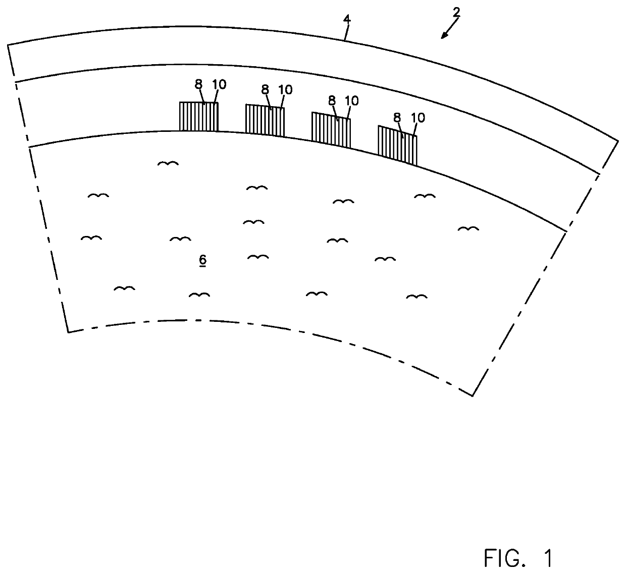
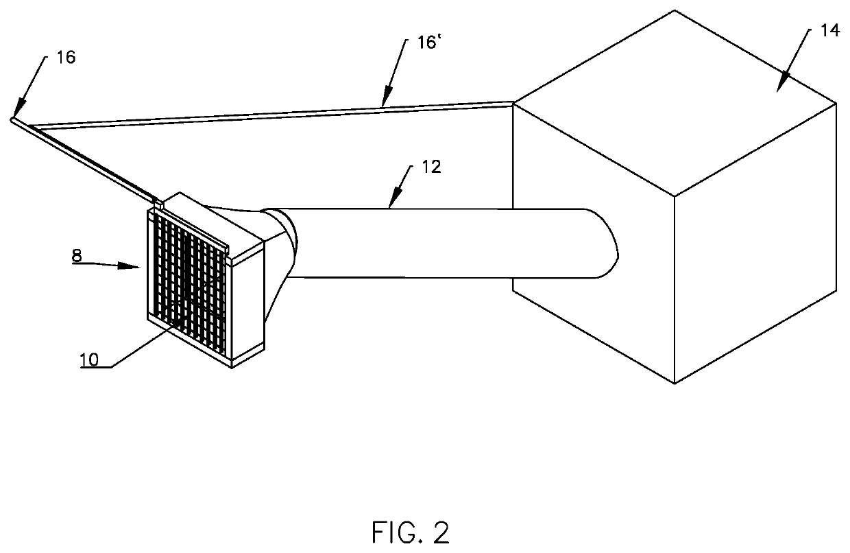
[0119]In a restricted area of a hydropower plant in Norway, an inlet screen having prior art electrically heated metal bars was mounted in front of the water inlets. The prior art bars were provided with resistance electrodes connected to a source of electricity, i.e. the prior art bars were directly heated by the resistance electrodes. The length of the metal bars was 12 meters. About 8 meters of the bars were arranged vertically below the water surface of the dam, while 4 meters of the bars were arranged above the water surface.

[0120]In order to remove frazil ice, the necessary electric effect was 1.5 MW.

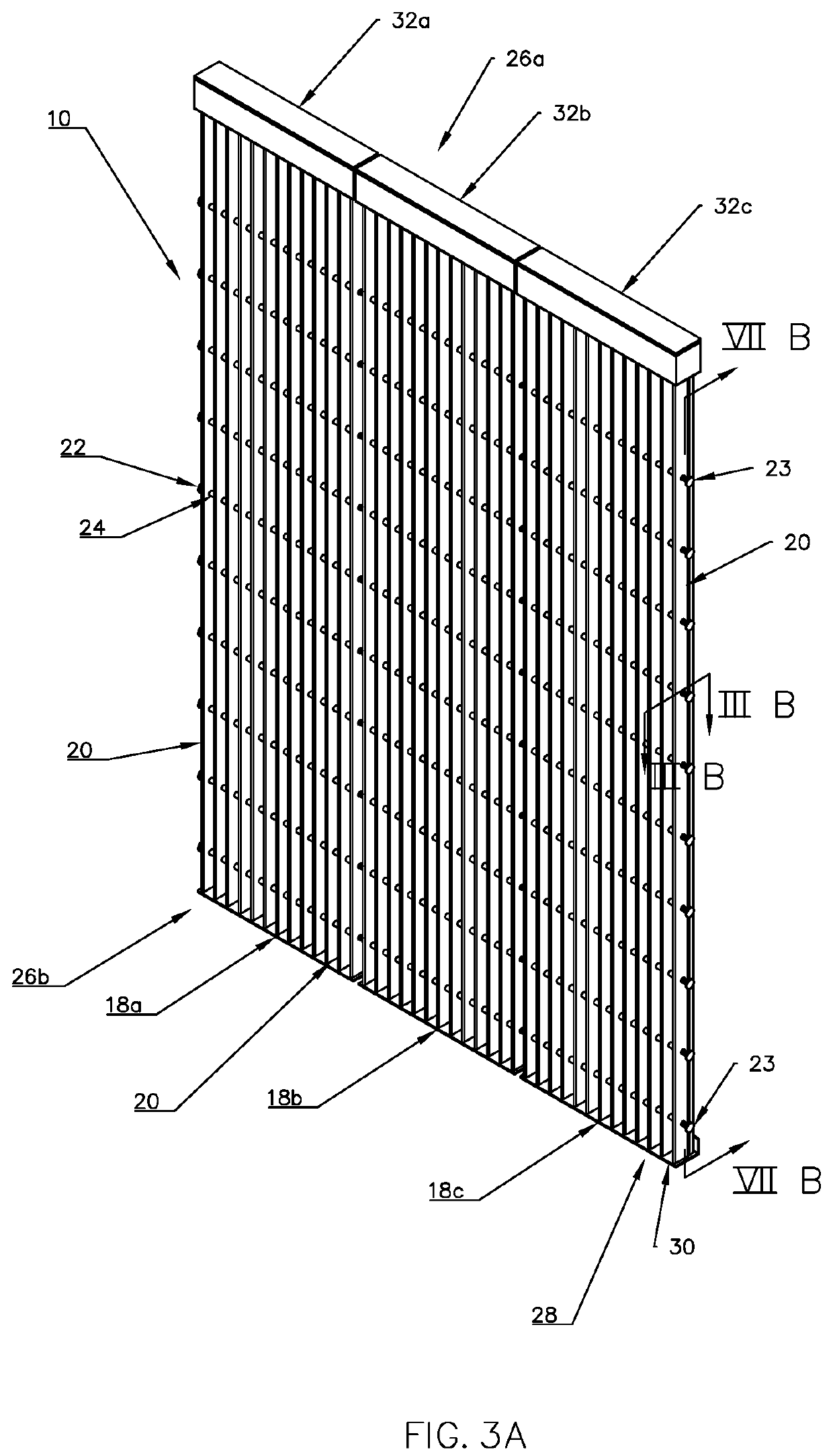
[0121]In the same restricted area of the hydropower plant, the prior art bars were exchanged for the bars 20 according to the invention, and were thus installed in front of the water inlets 8 of the same hydropower plant. The bars 20 according to the invention were also 12 meters long and extended 8 meters vertically below the water surface. Electric heating members 37 and a liqui...


PUM

PropertyMeasurementUnit
Electrical conductoraaaaaaaaaa
Freezing pointaaaaaaaaaa
Distanceaaaaaaaaaa

Abstract

The present invention relates to an inlet screen adapted to be arranged at the water inlet (8) of a hydropower plant and comprises a plurality of elongated bars (20), said bars (20) being separated by a distance holding means, each elongated bar (20) having in its elongation a proximal portion and a distal portion, and an upstream region and a downstream region, said upstream and downstream regions being at an angle in relation to said proximal and distal portions, at least one of said bars (20) defining a space (36; 36a) extending along at least a portion of the elongation of said bar (20), said bar (20) being provided with an electric heating means (31). In accordance with the invention, said elongated bar has an elongated intermediate portion (38a), said space (36; 36a) being defined in either of the upstream region (35a) and the downstream region (35b), said intermediate portion (38a) extending along the elongation of the bar (20) between the upstream region (35a) and the downstream region (35b), said electric heating means (31) comprising at least one electric heating member (37) being introduced into said space (36; 36a).

Description

TECHNICAL BACKGROUND OF THE INVENTION[0001]The present invention relates to an inlet screen adapted to be arranged at the water inlet of a hydropower plant, comprising a plurality of elongated bars, said bars being separated by a distance holding means, each elongated bar having in its elongation a proximal portion and a distal portion, and an upstream region and a downstream region, said upstream and downstream regions being at an angle in relation to said proximal and distal portions, at least one of said bars defining a space extending along at least a portion of the elongation of said bar, said bar being provided with an electric heating means.[0002]It also relates to a hydropower plant comprising to such an inlet screen in front of the water inlet of a turbine, wherein the bars are arranged in such way that the distal portion of the bars is underneath the water surface, said proximal portion being arranged at, above or underneath the water surface above the water surface.[0003]...

Claims


Application Information

Patent Timeline
IPC IPC(8): F03B11/08B01D29/44B01D35/18B01D29/60
CPCF03B11/08B01D29/608B01D35/18B01D29/445E02B5/085Y02E10/20E02B1/003E02B9/04E02B5/08
Inventor FASSELAND, JOHAN ARNT
Owner FASSELAND MEKANISKE VERKSTED AS
Features
  • Generate Ideas
  • Intellectual Property
  • Life Sciences
  • Materials
  • Tech Scout
  • Unparalleled Data Quality
  • Higher Quality Content
  • 60% Fewer Hallucinations
Learn More