
High temperature gas-cooled reactor core

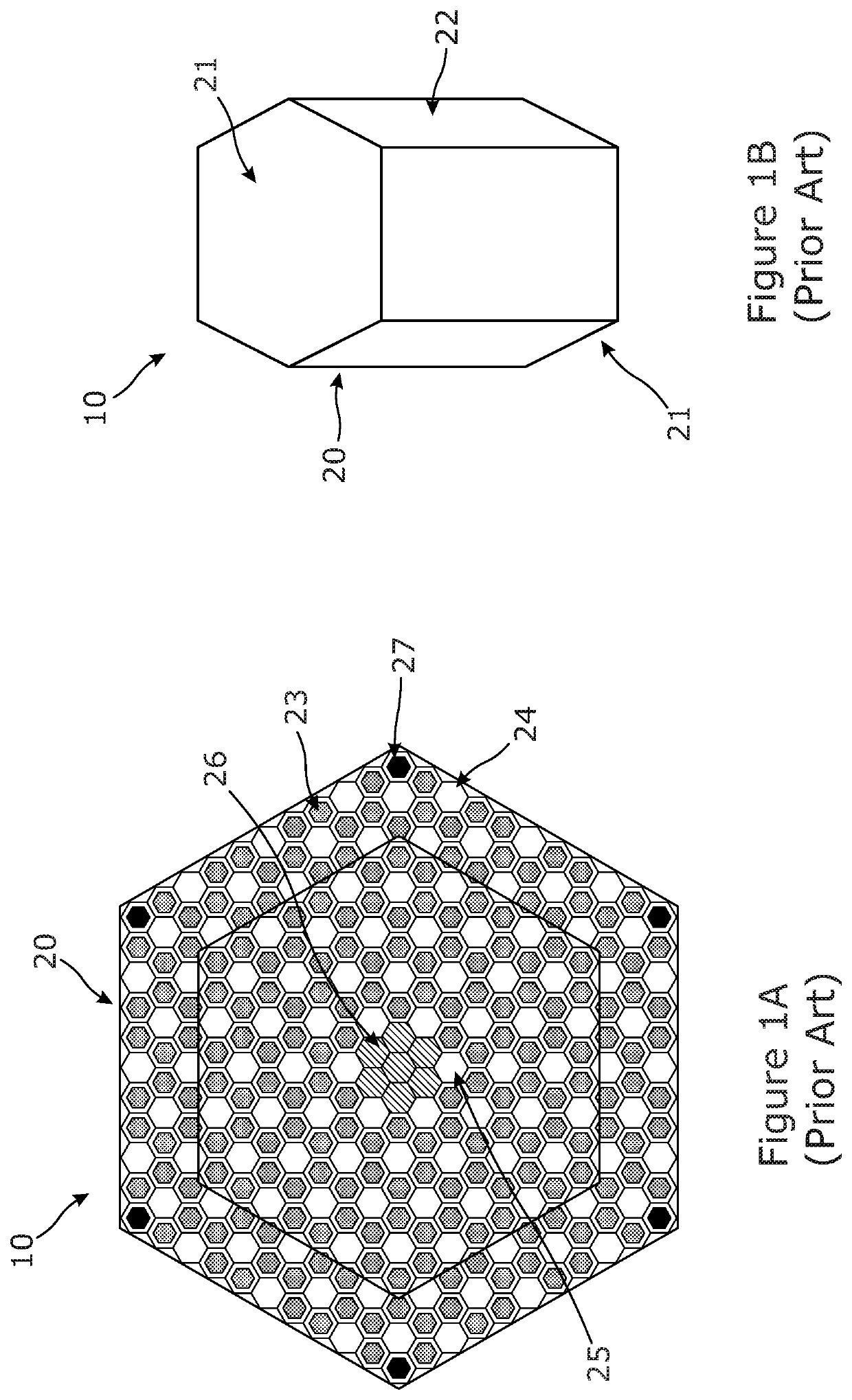
a gas-cooled, reactor core technology, applied in nuclear engineering, nuclear elements, greenhouse gas reduction, etc., can solve the problems of unsatisfactory use of moderators in fast neutron reactors, unsatisfactory fuel usage, etc., to facilitate a more complex reactor core geometry, reduce and facilitate the effect of reducing the weight of fuel elements

Active Publication Date: 2021-12-02
U BATTERY LTD
View PDF0 Cites 2 Cited by
  • Summary
  • Abstract
  • Description
  • Claims
  • Application Information

AI Technical Summary

Benefits of technology

The patent describes a new fuel element design for a nuclear reactor that allows for greater flexibility in arranging the fuel elements within the reactor core. The fuel elements are tall and thin, making them easy to arrange in a multi-lobed prism configuration. This design allows for more efficient placement and arrangement of the moderator material, which is important in a high temperature gas-cooled reactor. The fuel element design also reduces the weight and lifting capability required for the fuel handling machine, reducing cost and complexity. The total cross-sectional area of the fuel channels in a plane parallel to the bases of the prismatic fuel element may be no more than 24% of the cross-sectional area of the prismatic fuel element. This helps to increase the ratio of moderator material to fuel within the fuel element. Overall, this design allows for a more complex reactor core geometry to be constructed within a limited space, making it more efficient and cost-effective.

Problems solved by technology

A significant difference between fast neutron reactors and HTGRs is that fast neutron reactors do not require the use of neutron moderators and, indeed, the use of moderator in fast neutron reactors is undesirable.
It has been known for a long time in the field of HTGR design and operation that the existing fuel element and reactor core designs are slightly under moderated such that the fuel usage is not as efficient as it might be.

Method used


Image

  • High temperature gas-cooled reactor core
  • High temperature gas-cooled reactor core
  • High temperature gas-cooled reactor core

Examples


Embodiment Construction

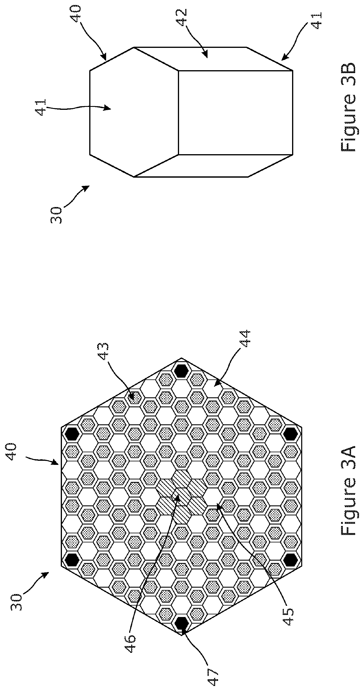
[0042]FIGS. 3A and 3B show a new design of fuel element 30. The fuel element 30 includes an elongate prismatic body 40 having opposing parallel bases 41 at either end of the prismatic body 40 and six sidewalls 42 extending between the bases 41. The cross-section of the prismatic body 40 in a plane parallel to the bases 41 is a regular hexagon. In one embodiment, the hexagonal cross-section of the prismatic body has an across-the-flats dimension of about 25.9 cm such that the surface area of the cross-section is about 581 cm2, but this is only an example. Typically, in embodiments of the disclosure, the cross-sectional area of the prismatic fuel element in a plane parallel to the bases of the prismatic fuel element may be within the range of between 500 cm2 and 800 cm2, and is no more than 675 cm2.

[0043]The elongate prismatic body 40 has a length (distance between the bases 41) of about 80 cm such that it is taller than it is wide. With a height of about 80 cm and an across-the-flats...


PUM


Abstract

The disclosure relates to a high temperature gas-cooled reactor core including a plurality of elongate fuel elements arranged in the form of a multi-lobed prism. Each prismatic fuel element includes an elongate prismatic body and a plurality of elongate fuel channels located within the prismatic body, wherein the cross-sectional area of each prismatic fuel element in a plane parallel to the bases of the prismatic fuel element is no more than 800 cm2 and wherein a ratio of the height of the prismatic body to its greatest width is greater than or equal to 3.0.

Description

CROSS REFERENCE TO RELATED APPLICATIONS[0001]This patent application claims the benefit and priority of Great Britain Patent Application No. 2008290.5 filed on Jun. 2, 2020, the disclosure of which is incorporated by reference herein in its entirety as part of the present application.BACKGROUND[0002]The present disclosure relates to a high temperature gas-cooled reactor core. The disclosure also relates to fuel elements and fuel element arrangements for high temperature gas-cooled reactors (HTGRs).[0003]HTGRs were first developed in the frame of a project initiated by the Organisation for Economic Co-operation and Development (OECD) in the 1960s that resulted in the design, construction, and operation of the Dragon reactor, the world's first HTGR. During the Dragon project, a new type of nuclear fuel was developed known as Coated Particle Fuel. This fuel includes very small spheres of fissile material, typically 350-750 microns in diameter, coated with ceramic layers composed of car...

Claims


Application Information

Patent Timeline
Patent Type & Authority Applications(United States)
IPC IPC(8): G21C3/04G21C3/28G21C15/06
CPCG21C3/042G21C15/06G21C3/28G21C5/14G21C5/02G21C3/322G21C3/328Y02E30/30G21C3/02G21C3/32
Inventor WOLODZKO, KORNELIAABRAM, TIMOTHY JAMES
Owner U BATTERY LTD
Learn More