Method and system for adaptive beamforming of ultrasound signals
- Summary
- Abstract
- Description
- Claims
- Application Information
AI Technical Summary
Benefits of technology
Problems solved by technology
Method used
Image

Examples
Embodiment Construction
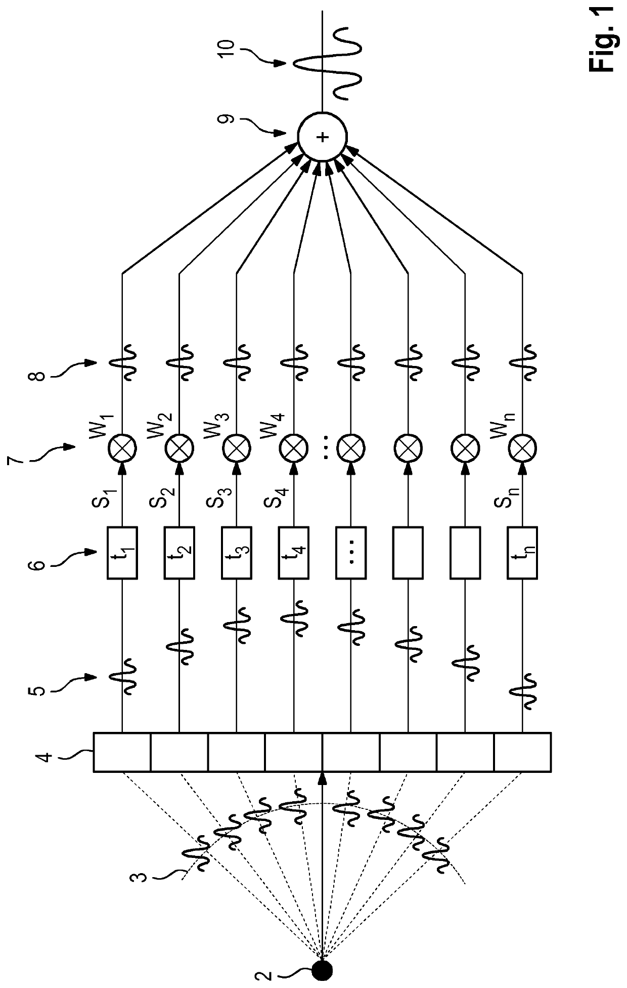
[0064]FIG. 1 illustrates conventional beamforming with the delay-and-sum (DAS) method. In response to e.g. an ultrasound pulse transmitted by an array 4 of transducer elements, echoes 3 are reflected from a point structure (focal point) 2 in the field-of-view. The echoes 3 are recorded by the array 4 of ultrasound transducers. The thus acquired raw RF signals 5 are also referred to channel data, each raw RF signal 5 having been acquired by one transducer element and thus relating to one channel. The example in FIG. 1 shows 8 channels. For beamforming, the channel data 5 are time-of-flight corrected in step 6, i.e. the different time shifts t1, t2, . . . , tn in which the echoes 3 were acquired by the array 4 are corrected for, depending on the geometry of the transducer array 4 and the focal point 2. These time-aligned RF signals S1 . . . Sn are then multiplied with apodization weights w1 . . . wn in step 7. In conventional DAS-beamforming, these weights are pre-set and not adapted ...
PUM
 Abstract
Description
Claims
Application Information
 - Generate Ideas
- Intellectual Property
- Life Sciences
- Materials
- Tech Scout
- Unparalleled Data Quality
- Higher Quality Content
- 60% Fewer Hallucinations
Browse by: Latest US Patents, China's latest patents, Technical Efficacy Thesaurus, Application Domain, Technology Topic, Popular Technical Reports.
© 2025 PatSnap. All rights reserved.Legal|Privacy policy|Modern Slavery Act Transparency Statement|Sitemap|About US| Contact US: help@patsnap.com