Supercharge Your Innovation With Domain-Expert AI Agents!

Camera actuator and camera module comprising same

a technology of camera actuator and camera module, which is applied in the direction of camera focusing arrangement, printers, instruments, etc., can solve the problems of low power consumption, low cost, and image shake caused by camera shake that occurs more seriously while a shutter speed is slower, so as to prevent magnetic field interference, and high data precision

Pending Publication Date: 2021-12-16
LG INNOTEK CO LTD
View PDF0 Cites 1 Cited by
  • Summary
  • Abstract
  • Description
  • Claims
  • Application Information

AI Technical Summary

Benefits of technology

The patent describes a camera actuator that prevents magnetic interference with a magnet for autofocus or zoom when implementing OIS (optical image stabilization) technology in a camera module used in advanced driver assistance systems. This is achieved by placing the magnet driving part on a separate camera actuator, which prevents interference between the two magnets. Additionally, the patent describes an ultra-small and ultra-thin camera actuator that takes advantage of a gyro sensor and a size control to achieve high data precision and is suitable for use in advanced driver assistance systems.

Problems solved by technology

Ultra-slim or ultra-thin issues, low power consumption, and low cost are major technical issues in the camera actuator.
In the mobile camera module, there are technical issues of realization of a high-performance module such as camera-shake correction or wide-angle optical system in addition to ultra-small and ultra-thin issues.
Therefore, in a darker environment, in a high-pixel camera, image shake due to camera shake that occurs while a shutter speed is slower occurs more seriously.
The conventional camera module 10 in which the OIS technology is adopted has a lens unit 12 mounted in an actuator 11, and since a mechanical driving device is required for moving a lens or tilting the module, there is a problem that a structure is complicated.
In addition, referring to FIG. 1, the conventional OIS technology may implement AF or Zoom at the same time as OIS driving, but a magnet for OIS and a magnet for AF or Zoom are disposed close to each other due to space limitation of a camera module and a position of a driving part of the conventional OIS technology, and cause a magnetic field interference, and thus there is a problem that the OIS driving is not performed normally, and a decent or a tilt phenomenon is induced, which causes problems with the accuracy of OIS data and affects the safety and life of drivers and pedestrians.
However, in order to increase the accuracy of data in OIS driving, the flatness of the gyro sensor is important, but there is a problem that it is difficult to reach a required accuracy level.
In addition, according to the related art, since the gyro sensor is disposed to be spaced apart from the camera module 10, it is difficult to accurately detect a degree of movement of the camera module according to the movement of the user.
For example, when the camera module 10 is rotated around the gyro sensor 15 by the user, a difference between a degree of movement of the gyro sensor 15 and a degree of movement of the actuator 11 or the lens unit 12 becomes large, and thus there is a problem that the accuracy of angular acceleration data is lowered.
In addition, recently, an ultra-slim and ultra-small camera module is required in accordance with technological trends, but since the ultra-small camera module has a space limitation for OIS drive, there is a problem that it is difficult to implement the OIS function applied to a general large camera, and there is a problem that the ultra-slim and ultra-small camera module cannot be implemented when the OIS drive is applied.
In addition, in the conventional OIS technology, an OIS driver is disposed at a side surface of a solid-state lens assembly within a limited camera module size, and thus there is a problem that it is difficult to secure a sufficient amount of light because a size of a lens to be subjected to OIS is limited.
Specifically, in order to achieve the best optical characteristics in a camera module, an alignment between the lens groups at the time of OIS implementation should be well matched through movement of a lens or tilting of a module, but in the conventional OIS technology, when a decenter in which a spherical center between the lens groups deviates from an optical axis or a tilt which is a phenomenon of lens tilt occurs, there is a problem that adversely affects image quality or resolution.
In addition, in the conventional OIS technology, since a mechanical driving device is required for moving the lens or tilting the module, there is a problem that a structure is complicated and power consumption is increased.

Method used


Image

  • Camera actuator and camera module comprising same
  • Camera actuator and camera module comprising same
  • Camera actuator and camera module comprising same

Examples


first embodiment

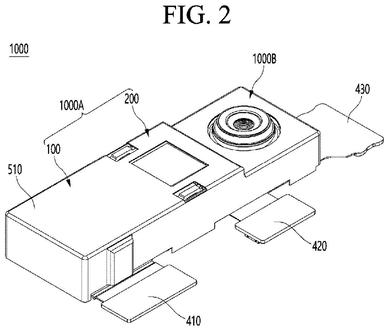
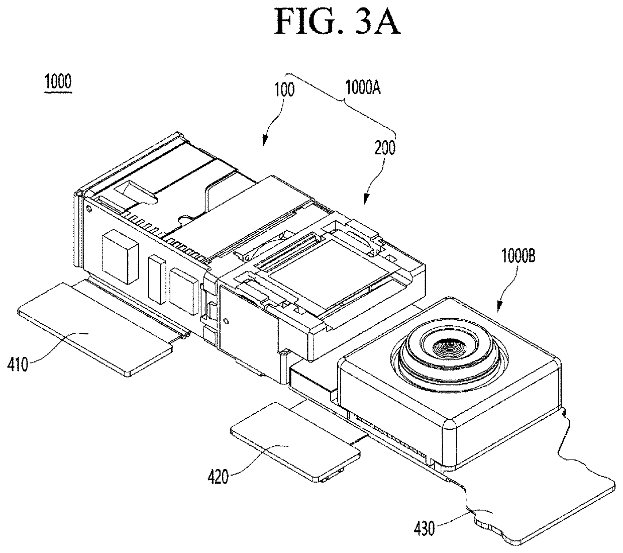
[0151]FIG. 2 is a perspective view showing a camera module 1000 of an embodiment, FIG. 3A is a perspective view of a shield can 510 removed from the camera module 1000 of the embodiment shown in FIG. 2, and FIG. 3B is a plan view of the camera module 1000 of the embodiment shown in FIG. 3A.

[0152]First, referring to FIG. 2, the camera module 1000 according to the embodiment may include a single or a plurality of camera modules. For example, the embodiment may include a first camera module 1000A and a second camera module 1000B. The first camera module 1000A and the second camera module 1000B may be covered by a predetermined shield can 510.

[0153]Referring to FIGS. 2, 3A, and 3B together, in an embodiment, the first camera module 1000A may include a single or a plurality of camera actuators. For example, the first camera module 1000A of the embodiment may include a first camera actuator 100 and a second camera actuator 200.

[0154]The first camera actuator 100 may be electrically connec...


PUM


Abstract

An embodiment relates to a camera actuator and a camera module comprising same. A camera actuator according to an embodiment may comprise: a housing; a base which is coupled to the housing and on which a lens assembly is disposed; a shaper unit disposed in the housing; a first driving part coupled to the shaper unit; and a prism unit coupled to the housing. The housing may comprise a housing body having an opening formed therethrough and a housing side part extending from the housing body. The first driving part may be disposed to overlap with the prism unit in the direction vertical to an optical axis.

Description

TECHNICAL FIELD[0001]Embodiments relate to a camera actuator and a camera module including the same.BACKGROUND ART[0002]A camera module performs a function of photographing a subject and storing the subject as an image or a moving image, and is mounted on a mobile terminal such as a mobile phone, a laptop, a drone, a vehicle, and the like.[0003]A camera actuator is a product that quickly focuses by moving a lens in the camera module up, down, left, and right. Ultra-slim or ultra-thin issues, low power consumption, and low cost are major technical issues in the camera actuator.[0004]Such a camera module is applied to a mobile camera module, a camera module for a vehicle, or the like.[0005]The mobile camera module is an essential part for taking and storing pictures in a mobile device such as a smart phone and a tablet PC. The mobile camera module converts light entering a lens into an electrical signal using an image sensor, outputs pictures to a device display through software, and ...

Claims


Application Information

Patent Timeline
Patent Type & Authority Applications(United States)
IPC IPC(8): G02B7/09G02B27/64G03B5/00G02B7/02
CPCG02B7/09G02B27/646G03B2205/0007G02B7/021G03B5/00G02B3/12G02B13/001G03B5/04G03B3/02G03B2205/0046G03B30/00G03B2205/0069G03B13/36G03B2205/003
Inventor JANG, DAE SIK
Owner LG INNOTEK CO LTD
Features
  • R&D
  • Intellectual Property
  • Life Sciences
  • Materials
  • Tech Scout
  • Unparalleled Data Quality
  • Higher Quality Content
  • 60% Fewer Hallucinations
Learn More