Method for producing a joint connection between a light-giving/optics plastic component and a metal component
- Summary
- Abstract
- Description
- Claims
- Application Information
AI Technical Summary
Benefits of technology
Problems solved by technology
Method used
Image
Examples
Embodiment Construction
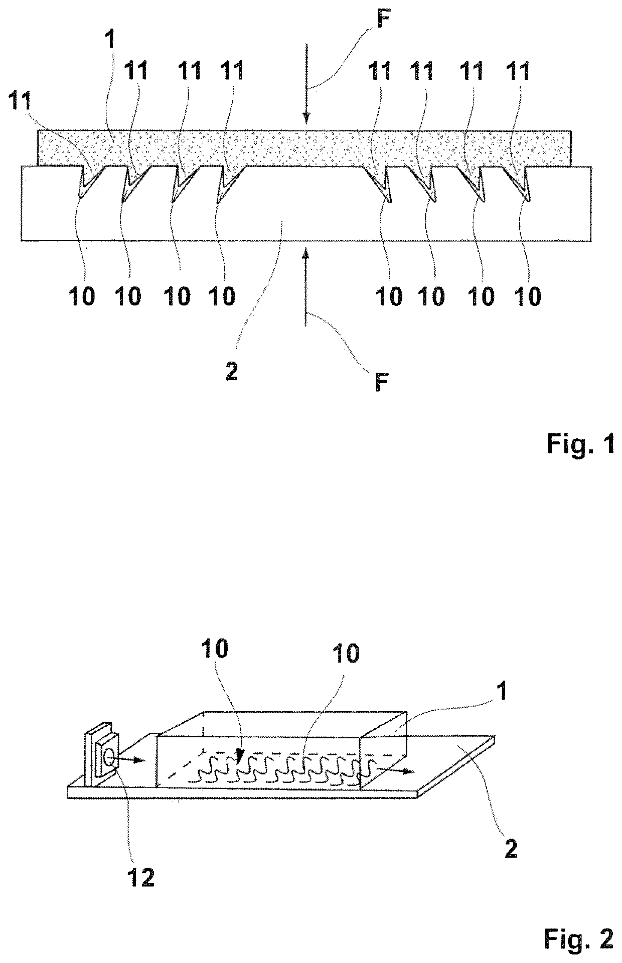
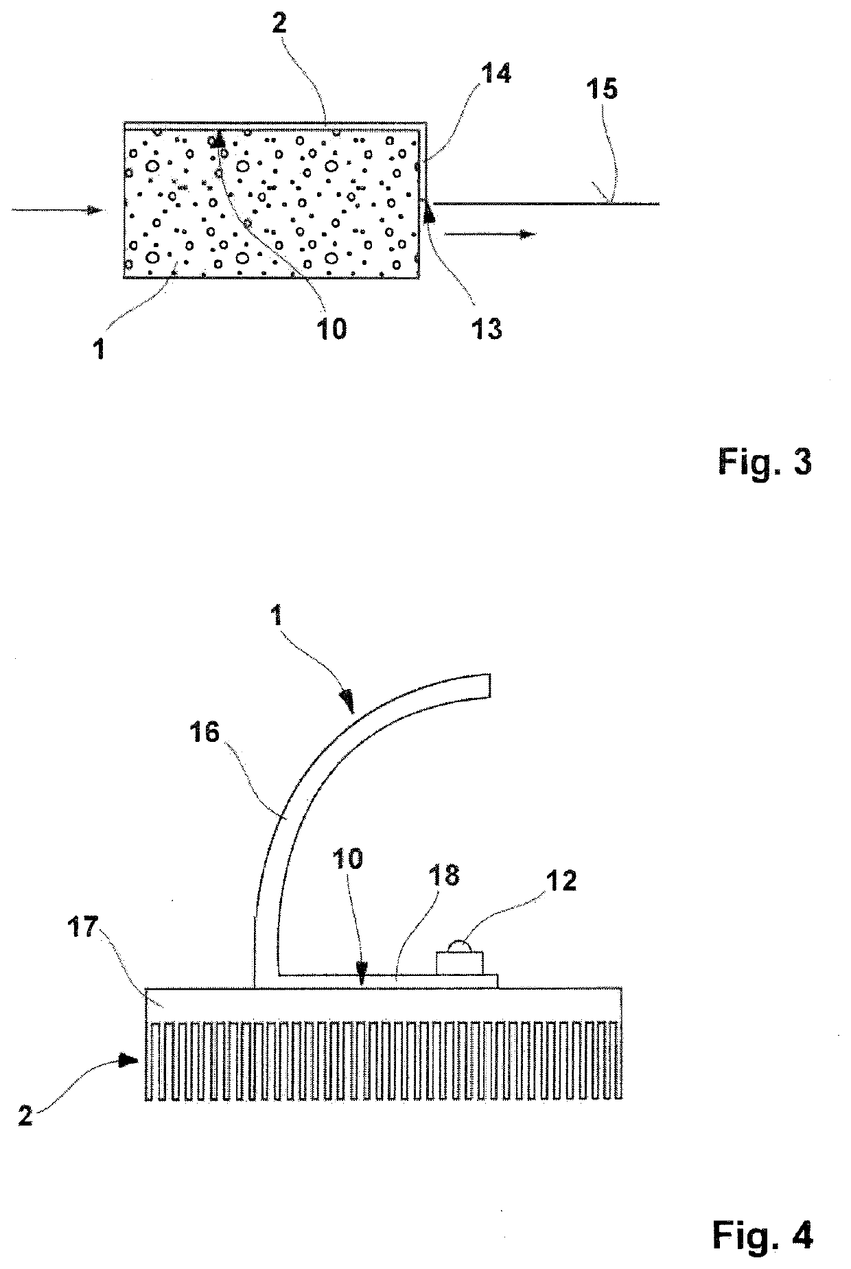
[0032]FIG. 1 shows a cross-sectional view of a joint between a plastic part 1 and a metal component 2. Plastic part 1 is illustrated in an abstracted manner and is therefore provided with a luminously efficacious design, which is not shown in further detail, and describes, for example, a reflective or transmissive optical element of a light module in a lighting device of a vehicle, for example in a headlamp. Metal component 2 may be, for example, a holder, a diaphragm or another retrofit part of the reflective or transmissive optical element, for example a cooling body.
[0033]Microstructures 10, which run at an incline starting from the surface into the body of metal component 2, are introduced into the surface of metal component 2 used as a contact surface to plastic part 1, the angle of inclination of the microstructures pointing in different directions, discernibly illustrated by way of example with left-side microstructures 10, with right-side microstructures 10 oriented in the o...
PUM
| Property | Measurement | Unit |
|---|---|---|
| Size | aaaaa | aaaaa |
| Microstructure | aaaaa | aaaaa |
| Area | aaaaa | aaaaa |
Abstract
Description
Claims
Application Information
 - R&D
- Intellectual Property
- Life Sciences
- Materials
- Tech Scout
- Unparalleled Data Quality
- Higher Quality Content
- 60% Fewer Hallucinations
Browse by: Latest US Patents, China's latest patents, Technical Efficacy Thesaurus, Application Domain, Technology Topic, Popular Technical Reports.
© 2025 PatSnap. All rights reserved.Legal|Privacy policy|Modern Slavery Act Transparency Statement|Sitemap|About US| Contact US: help@patsnap.com


