Valve assembly and pressure control method

a valve assembly and valve control technology, applied in the direction of braking systems, braking components, transportation and packaging, etc., can solve the problems of limiting the service life of the valve assembly, reducing the service life of the entire valve assembly, so as to achieve fast and efficient pressure control, prolong the service life of the valve control device, and prolong the service life of the valv

Pending Publication Date: 2021-12-30
KNORR-BREMSE SYST FUER NUTZFAHRZEUGE GMBH
View PDF0 Cites 0 Cited by
  • Summary
  • Abstract
  • Description
  • Claims
  • Application Information

AI Technical Summary

Benefits of technology

The patent describes a valve assembly that can control pressure quickly and efficiently at an output port while ensuring the valves have a long service life. This is important for autonomous driving where the components are constantly exposed to a high load. The valve assembly achieves this by reducing the load on the second membrane, which is the membrane that controls the output. This reduces the risk of cracks forming in the membrane and allows for a higher service life of the entire module. Additionally, an ABS intervention can cause the valve to release the brakes for a short-term period to further improve safety. Overall, this valve assembly design improves the performance and durability of pressure control valves for automated driving.

Problems solved by technology

These pressure reductions are implemented, for example, by an outlet valve, wherein a membrane in the outlet valve with the current configuration is significantly loaded by this / these short-term pressure reduction(s), which at the same time limits the service life of the valve assembly.
Since the pressure at the input port P1 is often significantly greater than the pressure at the output port P2 when activating the ABS, this could lead to a considerable load on the second membrane 23, which separates the two pressures from each other.
This significantly shortens the service life of the entire valve assembly.
Replacing a single membrane is generally not economically sensible.

Method used


Image

  • Valve assembly and pressure control method
  • Valve assembly and pressure control method
  • Valve assembly and pressure control method

Examples


Embodiment Construction

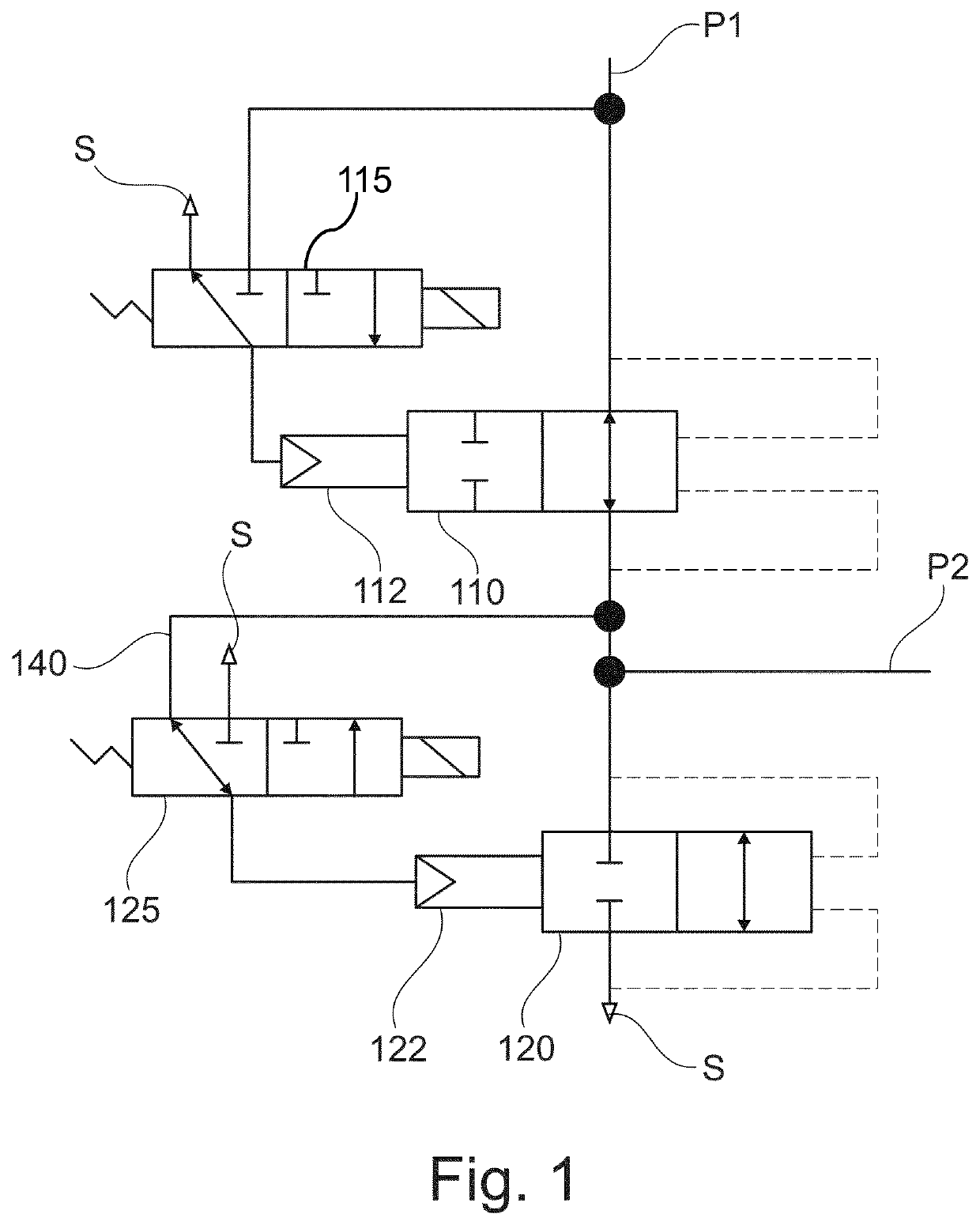
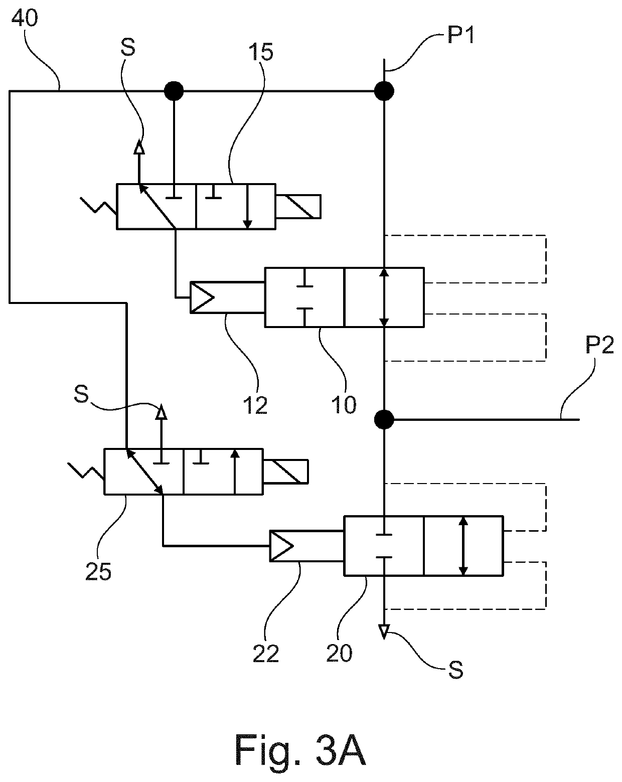
[0029]FIG. 1 shows a circuit diagram of a valve assembly for pressure control according to an exemplary embodiment of the present invention. As in the conventional valve assembly from FIG. 3A, a first valve 110 (for example a holding valve) and a second valve 120 (for example an outlet valve) are arranged in series between an input port P1 and a pressure sink S. The pressure sink S may have one or more openings to an environment or may include one or more areas with reduced pressure. The first valve 110 comprises a control input 112, which is connected to a first control valve 115. The first control valve 115 connects the control connection 112 of the first valve 110 either to the pressure sink S or to the input port P1. The second valve 120 also comprises a control input 122, which is controlled by a second control valve 125. The second control valve 125 connects the control connection 122 of the second valve 120 either to the pressure sink S or to the output port P2. The dashed li...


PUM


Abstract

A valve assembly for providing pressure control at an output port, including: an input port and the output port; a pressure sink; a first valve with a first control connection; a second valve with a second control connection, in which the first valve and the second valve are arranged in series between the input port and the pressure sink and between which the output port branches off; a first control valve to connect the first control connection to the input port or vents the first control connection in a controllable manner; and a second control valve to connect the first control connection to the output port or vents the first control connection in a controllable manner. Also described are a related anti-lock braking system, a commercial vehicle, and a method.

Description

FIELD OF THE INVENTION[0001]The present invention relates to a valve assembly and a method for pressure control at an output port, in particular to a valve assembly with an optimized air flow to increase its service life.BACKGROUND INFORMATION[0002]In anti-lock braking systems (ABS) of pneumatic braking systems for commercial vehicles, the pressure is substantially reduced for a short time during an ABS intervention, in order to remove a locking of the wheels or to release the brake for a short time. These pressure reductions are implemented, for example, by an outlet valve, wherein a membrane in the outlet valve with the current configuration is significantly loaded by this / these short-term pressure reduction(s), which at the same time limits the service life of the valve assembly.[0003]FIG. 3A and FIG. 3B show an example of such a valve assembly, which is used for ABS pressure control, wherein FIG. 3A shows a circuit diagram and FIG. 3B shows an exemplary implementation of the val...

Claims


Application Information

Patent Timeline
IPC IPC(8): B60T15/36B60T13/66B60T13/68B60T8/34B60T8/36
CPCB60T15/36B60T13/662B60T2270/10B60T8/342B60T8/362B60T13/683B60T8/3615B60T8/32B60T13/68B60T8/36B60T8/34
Inventor JONKMANN, RENÉKRUMREY, ALEXANDERKOENIG, ANDREAS
Owner KNORR-BREMSE SYST FUER NUTZFAHRZEUGE GMBH
Why Eureka
Try Eureka