Compressed-Air Treatment System and Method for Operating a Compressed-Air Treatment System

Active Publication Date: 2021-12-30
KNORR-BREMSE SYST FUER NUTZFAHRZEUGE GMBH
View PDF4 Cites 0 Cited by
  • Summary
  • Abstract
  • Description
  • Claims
  • Application Information

AI Technical Summary

Benefits of technology

[0021]By implementing the filling operation, the power-saving operation and the regeneration operation, there is no need for the compre

Problems solved by technology

This leads to increased energy consumption when the vehicle compressed air system is refilled.
However, there is the risk of an unwan

Method used


Image

  • Compressed-Air Treatment System and Method for Operating a Compressed-Air Treatment System
  • Compressed-Air Treatment System and Method for Operating a Compressed-Air Treatment System

Examples


Example

DETAILED DESCRIPTION OF THE DRAWINGS

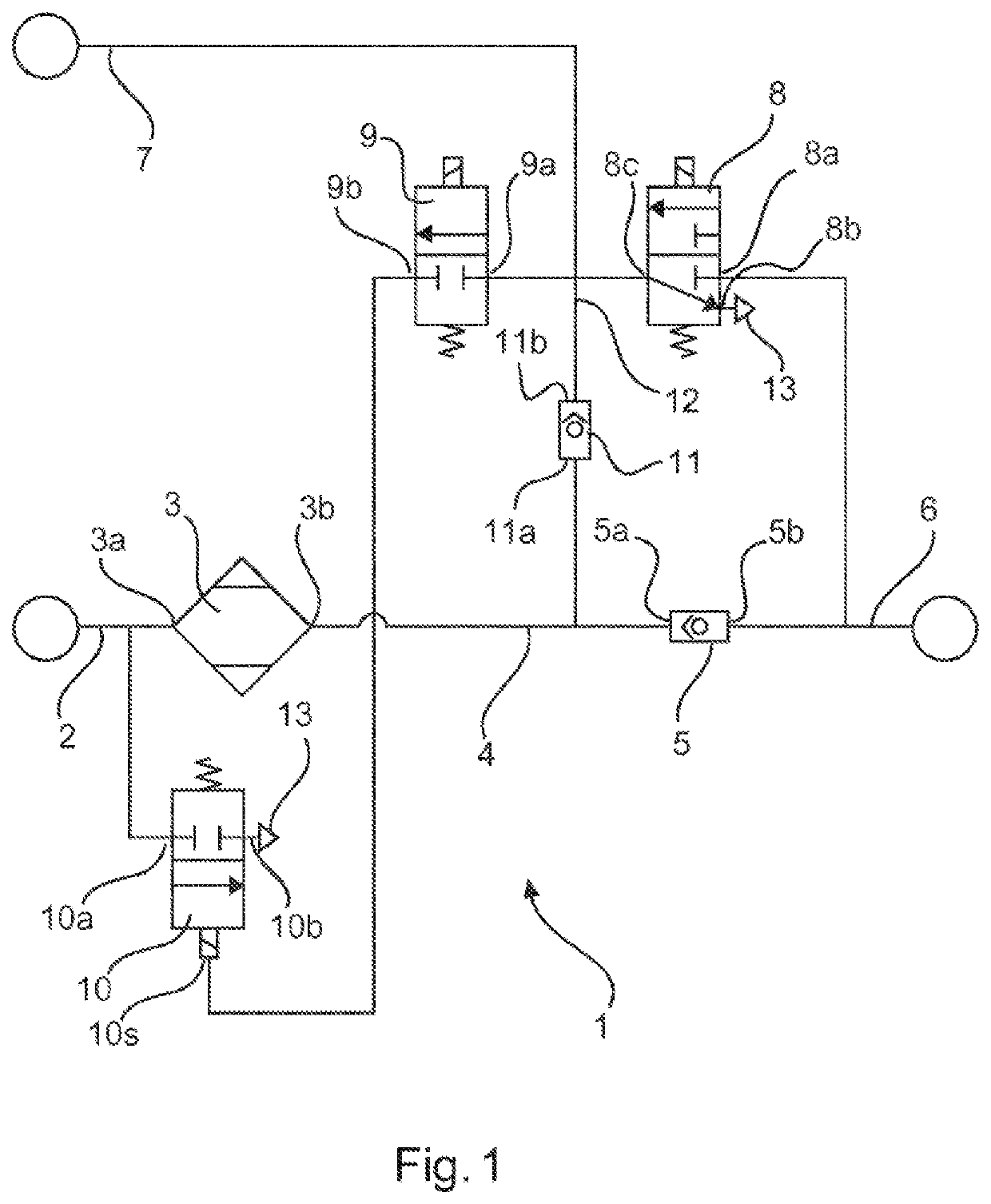
[0024]FIG. 1 shows a circuit diagram of a compressed-air treatment system 1 according to an embodiment of the invention.

[0025]The compressed-air treatment system 1 comprises a supply line 2 connected to a compressor which is not shown. In addition, the compressed-air treatment system 1 comprises an air dryer 3 with a first air dryer port 3a and a second air dryer port 3b, wherein the first air dryer port 3a is connected to the supply line 2.

[0026]Moreover, the compressed-air treatment system 1 comprises a connection line 4 which is connected to the second air dryer port 3b.

[0027]Moreover, a first check valve 5 with a first check valve port 5a and a second check valve port 5b is provided, wherein the first check valve port 5a is connected to the connection line 4. The first check valve 5 opens when there is an air flow from the connection line 4 via the first check valve 5 to the outlet line 6.

[0028]Furthermore, an outlet line 6 which is connected...


PUM


Abstract

A compressed-air treatment system and operating method are disclosed. The compressed-air treatment system has a first valve unit configured to charge a control line for a compressor with pressure and a pressure regulator valve unit configured to release pressure from a feed line, A control port of the pressure regulator valve unit is connectable to a second valve unit. A regeneration line which has a check valve for regeneration and which is utilized for a regeneration of a dryer cartridge is connected directly to the control line. During a filling operation the compressed-air treatment system is configured to release leakage air of the regeneration check valve via the first valve unit to surroundings. The filling operation is an operating state in which the compressor is activated to perform a supply of compressed air to a vehicle compressed-air system.

Description

BACKGROUND AND SUMMARY OF THE INVENTION[0001]The invention relates to a compressed-air treatment system and a method for operating the compressed-air treatment system, in particular a compressed-air treatment system and a method for operating the compressed-air treatment system which prevent a supply line from having to open after each load cycle.[0002]Compressed-air treatment systems are known in the art which treat compressed air for a vehicle compressed air system which has compressed air brakes or other actuators operated by compressed air. The vehicle compressed air system, or a part thereof, is opened after a corresponding load cycle, so that the compressed air escapes into the surrounding area. This leads to increased energy consumption when the vehicle compressed air system is refilled.[0003]For this reason, it was desirable for the vehicle compressed-air system with the compressed-air treatment system to be designed in such a manner that the vehicle compressed air system is...

Claims


Application Information

Patent Timeline
IPC IPC(8): F15B21/00F15B21/048F15B13/02
CPCF15B21/005F15B21/048F15B13/027F15B2211/3053F15B2211/88F15B2211/30505F15B13/024B60T17/004F15B21/041F15B2211/6658
Inventor ZEMAN, FERENC
Owner KNORR-BREMSE SYST FUER NUTZFAHRZEUGE GMBH
Why Eureka
Try Eureka