
Wet surface air cooler with counter current direct heat exchange section

Pending Publication Date: 2021-12-30
ALFA LAVAL CORP AB
View PDF5 Cites 0 Cited by
  • Summary
  • Abstract
  • Description
  • Claims
  • Application Information

AI Technical Summary

Benefits of technology

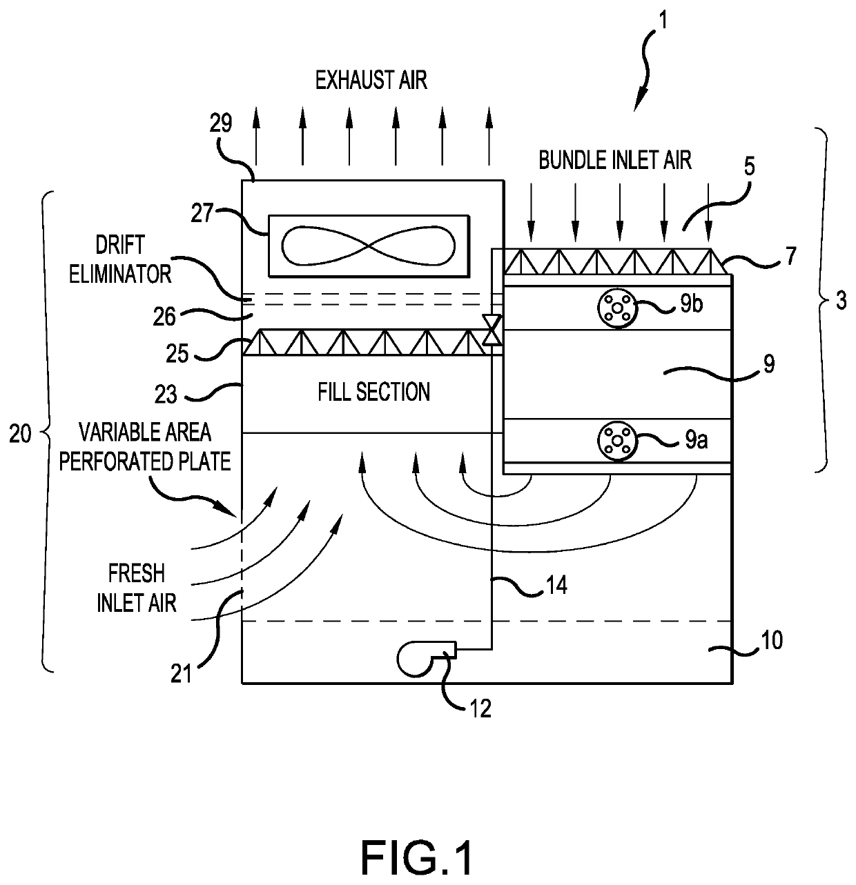
The invention described in this patent improves the efficiency of an air conditioning unit by using a direct heat exchange section. This section is made up of a cooling tower fill under the fan of the unit. The warm water from the unit is collected in a basin and then pumped back over the coil to cool it. The cooled water then passes through a section filled with air which pulls air through the fill, creating a countercurrent effect. This improves the process of removing heat from the unit. The invention also combines the flow of exhaust air from the unit with fresh air to further enhance energy efficiency. Overall, the invention is smaller and more efficient than current offerings, making better use of surface area.

Problems solved by technology

Existing evaporative cooling technologies, such as existing wet surface air coolers for industrial applications, have a large footprint and high operating cost.

Method used


Image

  • Wet surface air cooler with counter current direct heat exchange section
  • Wet surface air cooler with counter current direct heat exchange section
  • Wet surface air cooler with counter current direct heat exchange section

Examples


Embodiment Construction

[0038]The present invention will now be described with reference to the accompanying drawings, wherein the same reference numerals have been used to identify the same or similar elements throughout the several views.

[0039]FIG. 1 is a cross-sectional view of a WSAC according to the present invention. The WSAC 1 includes an indirect cooling section 3 having a first inlet 5, a first nozzle assembly 7 and at least one tube bundle 9 (e.g., coil). The first inlet 5 may be disposed on a first top surface of the WSAC 1 and may be in the form of an opening or a plurality of openings for allowing air to pass through the first nozzle assembly 7 and the tube bundle 9.

[0040]The tube bundle may include an inlet 9a and an outlet 9b. The outlet 9b of the tube bundle may be positioned above the inlet 9a.

[0041]Hot process medium flows through the tube bundle 9, as known in the art. The hot process medium is cooled by the co-current flow of air, via the first inlet 5, and spray water, sprayed from th...


PUM


Abstract

A wet surface air cooler (WSAC), including a tube bundle having a process medium therein, a first inlet, a nozzle assembly positioned adjacent to the first inlet for spraying water over the tube bundle to cool the process medium, an outlet, a fill section spaced from the tube bundle and positioned directly below the outlet, a second inlet provided in an outer wall of the WSAC and positioned below the fill section, the second inlet being configured to provide air from outside the WSAC to the fill section, a fan assembly for causing cause air to flow through the inlet, then past the tube bundle, to be mixed with air flowing through the second inlet, and out the outlet, and a basin extending an entire width of the WSAC for receiving water sprayed from the nozzle assembly.

Description

BACKGROUND OF THE INVENTION1. Field of Invention[0001]The present invention is directed to a wet surface air cooler (WSAC) having improved energy efficiency and improved thermal performance.2. Description of the Background Art[0002]Existing evaporative cooling technologies, such as existing wet surface air coolers for industrial applications, have a large footprint and high operating cost.[0003]A traditional WSAC (e.g., evaporative cooler) is comprised of a tube bundle for facilitating process fluid flow, a spray system that distributes water over a top of the tube bundle, and a fan or a set of fans that pulls air through the tube bundle. The air / spray water mixture on the outside surfaces of the tubes provides an evaporative cooling effect that removes heat from the process fluid and then rejects the heat out of both the fan stack and back into the spray water collection basin.[0004]For instance, U.S. Pat. No. 6,598,862 (herein “862 patent”), which is incorporated by reference in i...

Claims


Application Information

Patent Timeline
IPC IPC(8): F24F5/00
CPCF24F5/0035F28C1/14F28D5/02F28C1/16F28C2001/145F28C1/02F28F25/12F28F27/003Y02B30/70
Inventor PAWLAK, CHRISTIANSHAHRPASS, KEVIN
Owner ALFA LAVAL CORP AB
Learn More