
Omni-directional computerized numerical control (CNC) machine tool and method of performing the same

a computerized numerical control and machine tool technology, applied in the direction of metal-working holders, supporters, positioning apparatuses, etc., can solve the problems of high incidence of skilled workers, increased machining costs, and therefore the cost of finished workpieces, and achieves reduced production costs, reduced manufacturing costs, and simple hardware and software design.

Pending Publication Date: 2021-12-30
NGUYEN HOAI THANH
View PDF0 Cites 2 Cited by
  • Summary
  • Abstract
  • Description
  • Claims
  • Application Information

AI Technical Summary

Benefits of technology

The present invention provides a CNC machining apparatus that is precise, easy to operate, has simple hardware and software designs, requires less parts, and can operate on all surfaces of a workpiece without reloading.

Problems solved by technology

When a limited series of workpieces must be machined, i.e., when limited batches of identical workpiece clamping members are required, resulting in a high incidence of skilled workers and extensive machine downtime, both factors resulting in an increase in machining costs and therefore in the cost of the finished workpiece.
However, all of them are cumbersome and expensive.
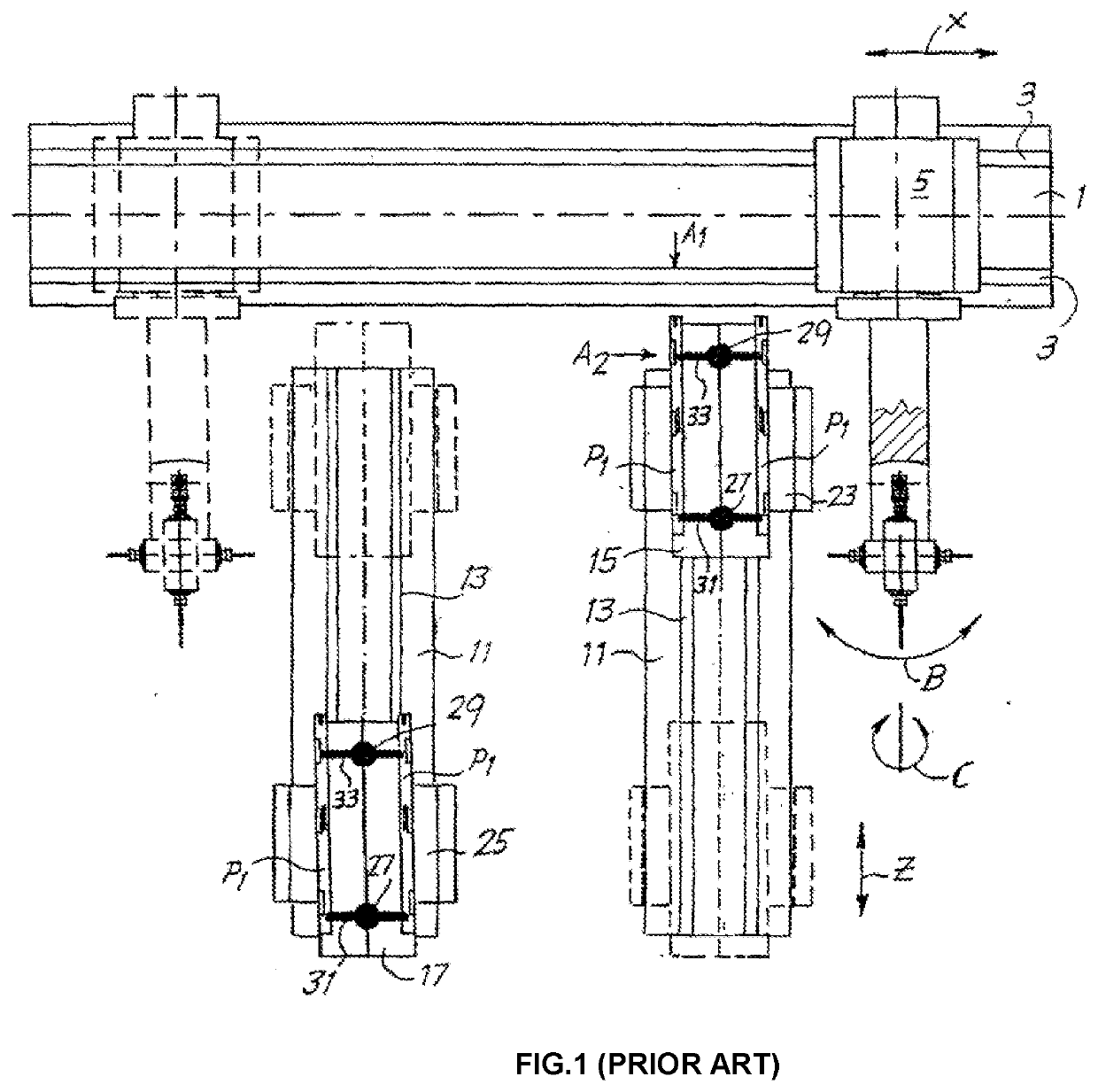
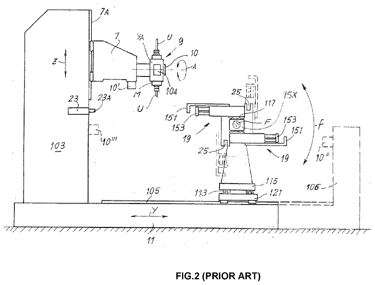
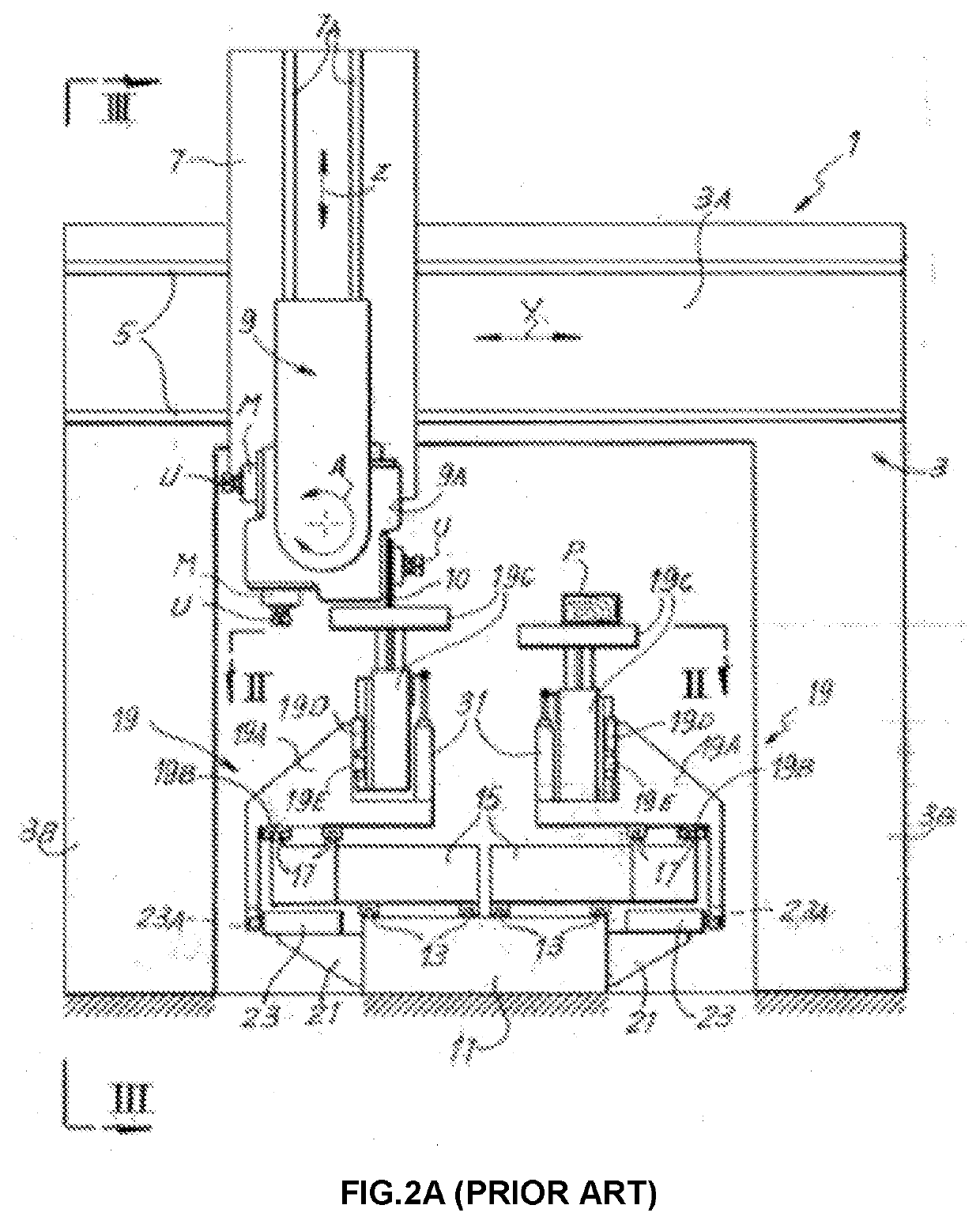
The prior-art CNC machine tools are cumbersome because the tool heads have to either (a) lower / rotate themselves to work on the bottom side of the workpiece or (b) the arms that hold the workpiece have to lift the workpiece up higher than the tool head.
In the Bacci's 811 application, the support rotates around the first axis C (see FIG. 6 of the Baccci's 811 application) to bring the first spindle group 14 underneath workpiece P. Obviously, the CNC with multi-spindle working head disclosed by the Bacci's 811 application is complex, expensive, and has limited applications because it requires multiple spindle groups and can only work on short workpieces P. This design cannot reach the distal ends of long workpieces.
The prior-art Bacci's 263 patent application does not teach a continuous rotation of the workpiece.
This results in the lack of precision when the workpiece needs to be worked on exact locations on its sides.

Method used


Image

  • Omni-directional computerized numerical control (CNC) machine tool and method of performing the same
  • Omni-directional computerized numerical control (CNC) machine tool and method of performing the same
  • Omni-directional computerized numerical control (CNC) machine tool and method of performing the same

Examples


Embodiment Construction

[0035]Reference will now be made in detail to the preferred embodiments of the invention, examples of which are illustrated in the accompanying drawings. While the invention will be described in conjunction with the preferred embodiments, it will be understood that they are not intended to limit the invention to these embodiments. On the contrary, the invention is intended to cover alternatives, modifications and equivalents, which may be included within the spirit and scope of the invention as defined by the appended claims. Furthermore, in the following detailed description of the present invention, numerous specific details are set forth in order to provide a thorough understanding of the present invention. However, it will be obvious to one of ordinary skill in the art that the present invention may be practiced without these specific details. In other instances, well-known methods, procedures, components, and circuits have not been described in detail so as not to unnecessarily...


PUM


Abstract

A computer numerical control (CNC) machining apparatus and method are disclosed which comprise: a first base; a second base vertically perpendicular to the first base; a tool head support assembly having a tool head, connected to and move a tool head in an omni-directional; and a plurality of rotatable clamps configured to independently hold, release, and move a workpiece along the first base and independently rotate a workpiece 360° around itself.

Description

CLAIM OF PRIORITY[0001]This application claims priority under 35 U.S.C. § 102(d) of an application No. 1-2020-03813, filed on Jun. 30, 2020, in the Republic Socialist of Vietnam, entitled, “Máy gia công s{circumflex over (ó)} (CNC) vá pháp gia công trên máy này”. The patent application identified above is incorporated here by reference in its entirety.FIELD OF THE INVENTION[0002]The present invention relates generally to the field of computerized numerical controlled (CNC) machine tools. More specifically, the present invention relates to an omni-directional CNC machine tool that can rotate continually at an infinitesimal amount and work on any circumferential (rounded) surfaces and at any length.BACKGROUND ART[0003]Today computerized numeric controlled (CNC) machine tools armed with smart software systems and automated processes have become ubiquitous in the industrial sector. These machine tools have greatly reduced the traditionally tedious and backbreaking works for carpenter...

Claims


Application Information

Patent Timeline
Patent Type & Authority Applications(United States)
IPC IPC(8): G05B19/19B23Q3/155
CPCG05B19/19G05B2219/33099B23Q3/15513B23Q3/15503B23Q2240/007B23Q1/527B23Q1/012
Inventor NGUYEN, HOAI THANH
Owner NGUYEN HOAI THANH
Learn More