Lens attachment of reduced focus and increased light admittance
a technology of reduced focus and lens attachment, which is applied in the field of optical lens attachment of reduced focus and increased light admittance, can solve the problems of limited variety of adaptable objective lenses, limited chromatic aberration, field curvature and higher order coma, etc., and achieves compact structure, minimize aggravating chromatic aberration, and increased distance between the objective lens and the lens attachment
- Summary
- Abstract
- Description
- Claims
- Application Information
AI Technical Summary
Benefits of technology
Problems solved by technology
Method used
Image
Examples
embodiment 1
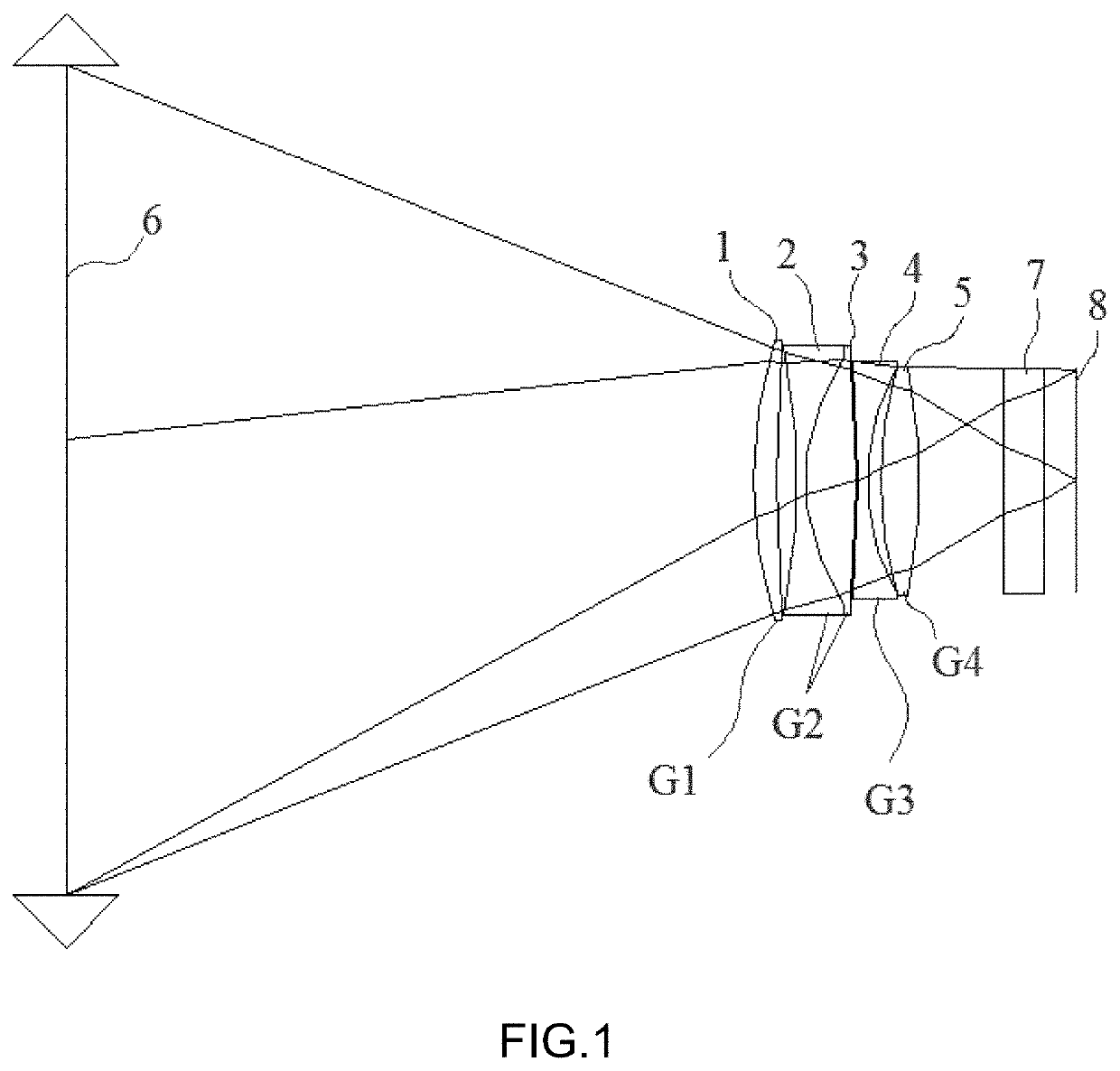
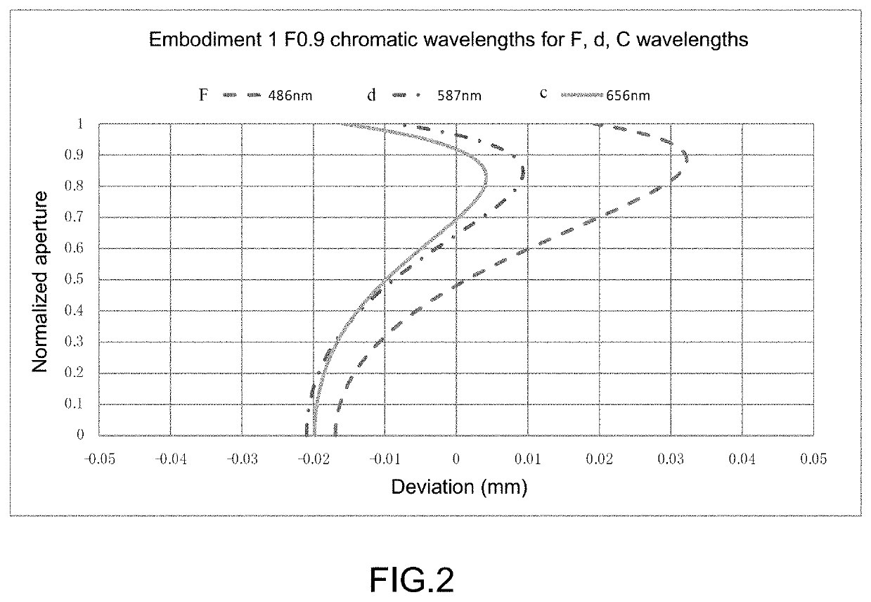
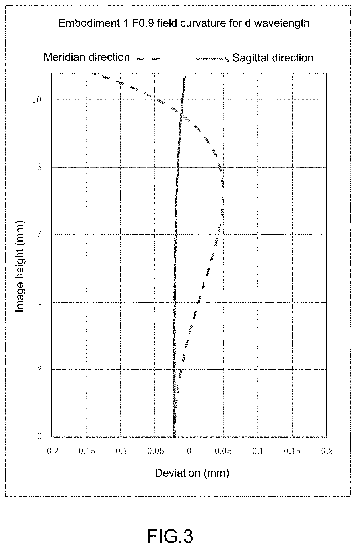
[0062]FIG. 1 illustrates embodiment 1 of the present invention, comprising a lens attachment of reduced focus and increased light admittance having 71.80 mm focal length and 0.71× magnification; the lens attachment comprises, in a sequential order from an object side to an image side, a first lens element 1 which is a crescent-shape spherical lens having a positive power wherein a front surface of the first lens element 1 is convex (bulging) towards the object side and a rear surface of the first lens element 1 is concave (depressed) towards the object side, a second lens element 2 which is a biconcave spherical lens having a negative power wherein a front surface of the second lens element 2 is concave (depressed) towards the image side and a rear surface of the second lens element 2 is concave (depressed) towards the object side, a third lens element 3 which is a biconvex spherical lens having a positive power wherein a front surface of the third lens element 3 is convex (bulging)...
embodiment 2
[0068]FIG. 8 illustrates embodiment 2 of the present invention, comprising a lens attachment of reduced focus and increased light admittance having 70.99 mm focal length and 0.71× magnification; the lens attachment comprises, in a sequential order from an object side to an image side, a first lens element 1 which is a crescent-shape spherical lens having a positive power wherein a front surface of the first lens element 1 is convex (bulging) towards the object side and a rear surface of the first lens element 1 is concave (depressed) towards the object side, a second lens element 2 which is a biconcave spherical lens having a negative power wherein a front surface of the second lens element 2 is concave (depressed) towards the image side and a rear surface of the second lens element 2 is concave (depressed) towards the object side, a third lens element 3 which is a biconvex spherical lens having a positive power wherein a front surface of the third lens element 3 is convex (bulging)...
embodiment 3
[0074]FIG. 15 illustrates embodiment 3 of the present invention, comprising a lens attachment of reduced focus and increased light admittance having 85.65 mm focal length and 0.71× magnification; the lens attachment comprises, in a sequential order from an object side to an image side, a first lens element 1 which is a crescent-shape spherical lens having a positive power wherein a front surface of the first lens element 1 is convex (bulging) towards the object side and a rear surface of the first lens element 1 is concave (depressed) towards the object side, a second lens element 2 which is a biconcave spherical lens having a negative power wherein a front surface of the second lens element 2 is concave (depressed) towards the image side and a rear surface of the second lens element 2 is concave (depressed) towards the object side, a third lens element 3 which is a biconvex spherical lens having a positive power wherein a front surface of the third lens element 3 is convex (bulging...
PUM
 Abstract
Description
Claims
Application Information
 - R&D
- Intellectual Property
- Life Sciences
- Materials
- Tech Scout
- Unparalleled Data Quality
- Higher Quality Content
- 60% Fewer Hallucinations
Browse by: Latest US Patents, China's latest patents, Technical Efficacy Thesaurus, Application Domain, Technology Topic, Popular Technical Reports.
© 2025 PatSnap. All rights reserved.Legal|Privacy policy|Modern Slavery Act Transparency Statement|Sitemap|About US| Contact US: help@patsnap.com


