High voltage interlock circuit and detection method thereof

a high-voltage interlocking circuit and detection method technology, applied in the field of new energy, can solve the problems that the safety of high-voltage vehicles cannot be ignored in the design of new-energy vehicles, affect damage the controller, etc., and achieve the effect of avoiding damage to the controller, accurate determination, and improving the accuracy of fault detection for high-voltage interlocking circuits

Active Publication Date: 2022-01-13
CONTEMPORARY AMPEREX TECH CO
View PDF0 Cites 6 Cited by
  • Summary
  • Abstract
  • Description
  • Claims
  • Application Information

AI Technical Summary

Benefits of technology

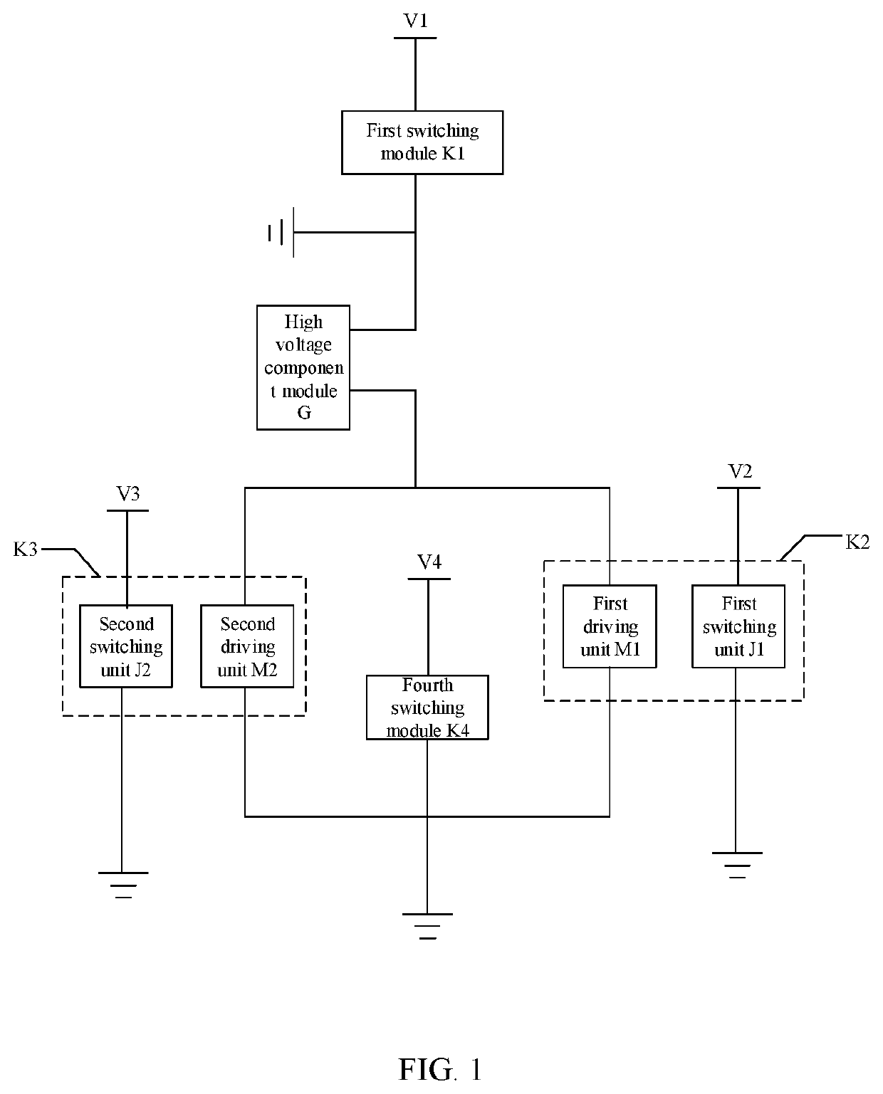
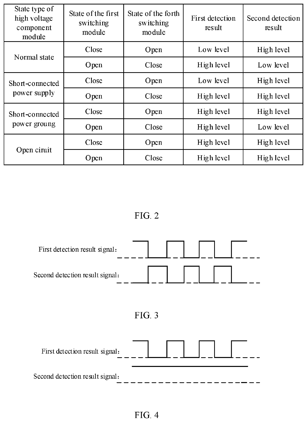
[0016]In the embodiments of the present application, a signal detection terminal may be isolated from the input terminal of the high voltage interlock circuit and the output terminal of the high voltage interlock circuit due to the isolation setting of the first driving unit and the first switching unit in the second switching module and the isolation setting of the second driving unit and the second switching unit in the third switching module, so as to avoid the damage to the controller caused by large external voltage from the shorting of the high voltage component module. Moreover, by using the first detection result and the second detection result obtained when the first switching module and the fourth switching module are alternately closed, the fault type of the high voltage component module can be accurately determined, and the accuracy of fault detection for the high voltage interlock circuit can be improved.

Problems solved by technology

The biggest difference between new energy vehicles and traditional vehicles is that new energy vehicles rely on high voltage and large current to provide power for vehicles, thus the high voltage safety problem cannot be ignored in the design of new energy vehicles.
When there is a large external voltage, it may damage the controller and affect the accuracy of fault detection.

Method used


Image

  • High voltage interlock circuit and detection method thereof
  • High voltage interlock circuit and detection method thereof
  • High voltage interlock circuit and detection method thereof

Examples


Embodiment Construction

[0026]The embodiments of the present application are further described in detail in combination with the drawings and the embodiments. The following detailed description and drawings of the embodiments are used to illustrate the principle of the application as example, but not to limit the scope of the application, that is, the application is not limited to the described embodiments.

[0027]In the description of the application, it is noted that unless otherwise specified, “multiple” means more than two; the orientation or position relationship indicated by the terms “up”, “down”, “left”, “right”, “inside”, “outside” is only for the convenience of describing the application and simplifying the description, rather than indicating or implying that the device or element referred to must have a specific orientation, be constructed and operated in a specific orientation, so it cannot be understood as a limitation of the application. In addition, the terms “first”, “second”, “third” and so ...


PUM


Abstract

The application discloses a high voltage interlock circuit and a detection method thereof. The circuit comprises: a first switching module; a second switching module, comprising a first driving unit and a first switching unit arranged in isolation, the first switching unit is arranged between a second power supply and a second power ground; a third switching module, comprising a second driving unit and a second switching unit arranged in isolation; a fourth switching module, arranged between the fourth power supply and the first power ground; a controller. The embodiments of the application improve the accuracy of fault detection.

Description

CROSS-REFERENCE TO RELATED APPLICATIONS[0001]The present application is a continuation of International Application No. PCT / CN2021 / 078723, filed on Mar. 2, 2021, which claims priority to Chinese patent application No. 202010444444.X entitled “HIGH VOLTAGE INTERLOCK CIRCUIT AND DETECTION METHOD THEREOF” filed on May 22, 2020, both of which are hereby incorporated by reference in their entireties.FIELD OF THE INVENTION[0002]The present application relates to the field of new energy, in particular to a high voltage interlock circuit and a detection method thereof.BACKGROUND OF THE INVENTION[0003]With the rapid development of new energy vehicles, people pay more and more attention to the safety of the new energy vehicles. The biggest difference between new energy vehicles and traditional vehicles is that new energy vehicles rely on high voltage and large current to provide power for vehicles, thus the high voltage safety problem cannot be ignored in the design of new energy vehicles. A ...

Claims


Application Information

Patent Timeline
Patent Type & Authority Applications(United States)
IPC IPC(8): B60L3/00H03K17/687
CPCB60L3/0023H03K17/6871G01R31/52G01R31/54G01R31/56G01R31/006Y02T10/70G01R19/16571
Inventor FU, YANHUIWU, GUOXIUDU, BAOHAILIU, CHANGJIAN
Owner CONTEMPORARY AMPEREX TECH CO
Why Eureka
Try Eureka