Method and system for controlling a turbomachine with control saturations management

Pending Publication Date: 2022-01-13
SN DETUDE & DE CONSTR DE MOTEURS DAVIATION S N E C M A
View PDF0 Cites 0 Cited by
  • Summary
  • Abstract
  • Description
  • Claims
  • Application Information

AI Technical Summary

Benefits of technology

[0018]The invention aims to propose a method and a system for controlling a turbomachine making it possible to

Problems solved by technology

However, to comply with the operational constraints of the turbomachine, the calculated fuel flow rate command WF may be saturated or not taken into account in some cases.
As each limiter acts on one command independently of the other command, the applied commands are no longer consistent relative to each other.
These cases pose problems for the decoupling.
If the value of a command is changed,

Method used


Image

  • Method and system for controlling a turbomachine with control saturations management
  • Method and system for controlling a turbomachine with control saturations management
  • Method and system for controlling a turbomachine with control saturations management

Examples


Embodiment Construction

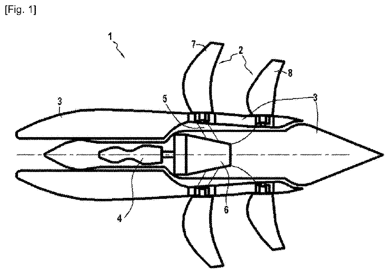
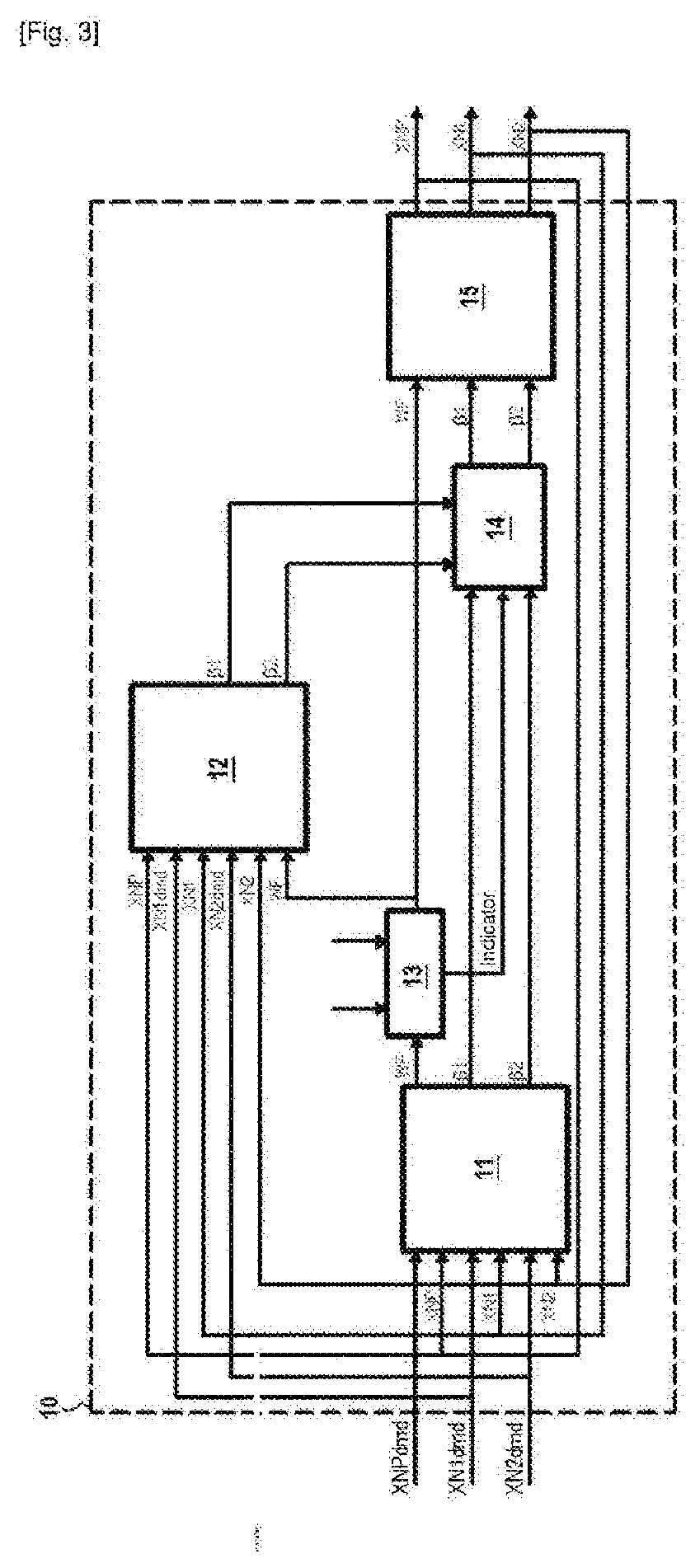
[0049]FIG. 3 is schematically represents a system for controlling 10 a turbomachine according to one embodiment of the invention. The turbomachine controlled by the control system 10 according to the invention may be a turbomachine 1 with unducted fan such as the one described in FIG. 2.

[0050]The control system 10 comprises a first corrector 11, a second corrector 12, a first selection unit 13, a second selection unit 14 and an integrator 15.

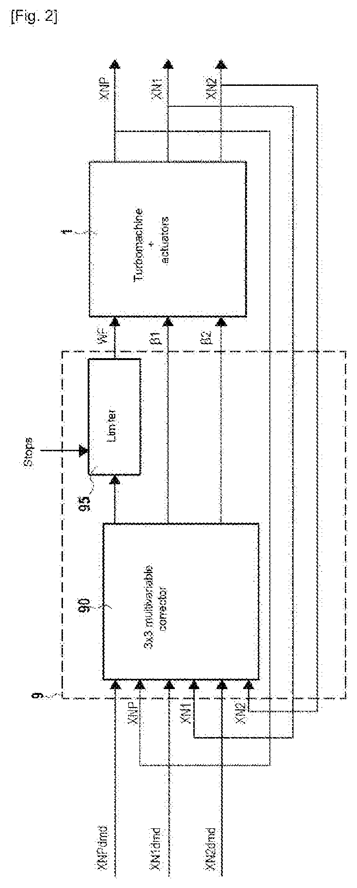
[0051]The first corrector 11 comprises three outputs delivering a first value for each of the three control quantities. The first control quantity corresponds to the fuel flow rate WF of the open rotor 1, the second control quantity corresponds to the pitch β1 of the upstream propeller of the open rotor 1 and the third control quantity corresponds to the pitch β2 of the downstream propeller of the open rotor 1.

[0052]The first corrector 11 receives as input the values of three variables of the open rotor 1, the first variable corresponding to the...


PUM


Abstract

Method for controlling a first, a second and a third variable of a turbomachine as a function of a first, a second and a third control quantity of a turbomachine which can each be saturated as a function of the operating parameters of the turbomachine.
The method comprises a first multivariable correction (120) delivering a first value for the three control quantities, a selection (130) of the first control quantity to be delivered as a function of a minimum value, of a maximum value and of the value determined by the first correction, a second multivariable correction (140) delivering a second value for the second and third control quantities, and a selection (150) of the values of the second and third control quantities to be delivered in the values determined during the first correction and those determined during the second correction.

Description

TECHNICAL FIELD[0001]The invention relates to the field of the systems for controlling turbomachines, in particular turboprop engines or turbomachines with unducted fan also known as Unducted Single Fan or USF.PRIOR ART[0002]FIG. 1 represents a turbomachine with unducted fan according to the state of the art, or unducted fan. As illustrated in FIG. 1, an unducted fan 1, also called open rotor, is an aircraft turbojet engine whose fan 2 is directly fixed to the power turbine and outside a nacelle 3, which allows increasing the bypass ratio of the engine compared to a ducted turbojet engine, and thus reducing fuel consumption.[0003]An open rotor is generally equipped with a gas generator 4 and with a free turbine 5 driving, via a reduction gearbox 6, two contra-rotating variable-pitch propellers 7 and 8.[0004]As illustrated in FIG. 2 which schematically represents a system for controlling an open rotor 1, an open rotor 1 can be considered from a command point of view as a multivariabl...

Claims


Application Information

Patent Timeline
IPC IPC(8): F02C9/00
CPCF02C9/00F05D2270/336F05D2220/323F02K3/04F02C3/04F02C9/48F01D7/00F02C9/58F05D2260/74F05D2270/304B64D31/06B64D2027/005Y02T50/60
Inventor RASLAIN, TYPHAINELE BRUN, CHRISTOPHE MARC ALEXANDRECLERMONTE, SYLVAIN
Owner SN DETUDE & DE CONSTR DE MOTEURS DAVIATION S N E C M A
Why Eureka
Try Eureka