
Systems and Methods For Advanced Well Access to Subterranean Formations

a technology of advanced wells and subterranean formations, applied in the field of advanced wells access systems and methods, can solve the problems of limiting the extent of enhanced recovery and/or abandonment operations, and limiting the rate at which wells may be drilled or completed, so as to improve the overall efficiency of various operational states, improve the effect of emergency deployment operations, and reduce costs and/or environmental impacts

Active Publication Date: 2013-11-14
EXXONMOBIL UPSTREAM RES CO
View PDF2 Cites 7 Cited by
  • Summary
  • Abstract
  • Description
  • Claims
  • Application Information

AI Technical Summary

Benefits of technology

The patent text describes systems and methods to reduce costs and environmental impacts on well operation and improve efficiency. This includes easing seasonal operational constraints, improving emergency deployment, and decreasing emergency response times. The systems and methods also facilitate low-cost, efficient plugging, abandonment, and killing operations, as well as advanced oil recovery techniques.

Problems solved by technology

Under certain circumstances, relying on a single point-of-entry for access between the surface region and the subterranean formation may be problematic, or at least inefficient.
As an illustrative, non-exclusive example, a well may be damaged or subjected to conditions in which it experiences an uncontrolled flow of fluid from the well, which also may be called a blowout.
Under these circumstances, the traditional, single point-of-entry well may not provide the level of access needed to stop the blowout, and other techniques may need to be utilized.
As another illustrative, non-exclusive example, single point-of-entry wells may limit the rate at which the well may be drilled or completed, and / or may limit enhanced recovery and / or abandonment operations due to the limitations of having only the single point-of-entry, especially with respect to the terminal depth(s) of the well's casing.

Method used


Image

  • Systems and Methods For Advanced Well Access to Subterranean Formations
  • Systems and Methods For Advanced Well Access to Subterranean Formations
  • Systems and Methods For Advanced Well Access to Subterranean Formations

Examples


Embodiment Construction

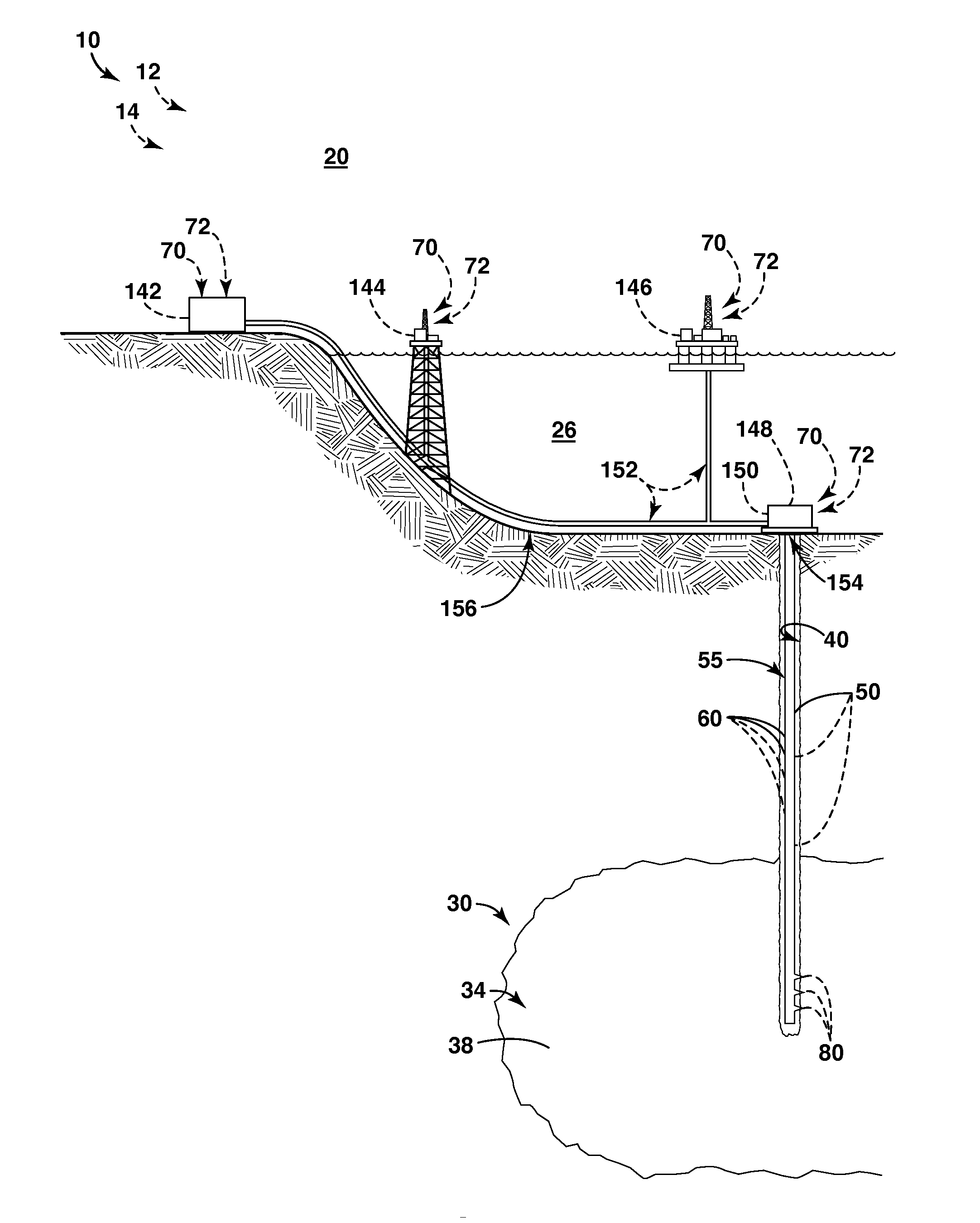
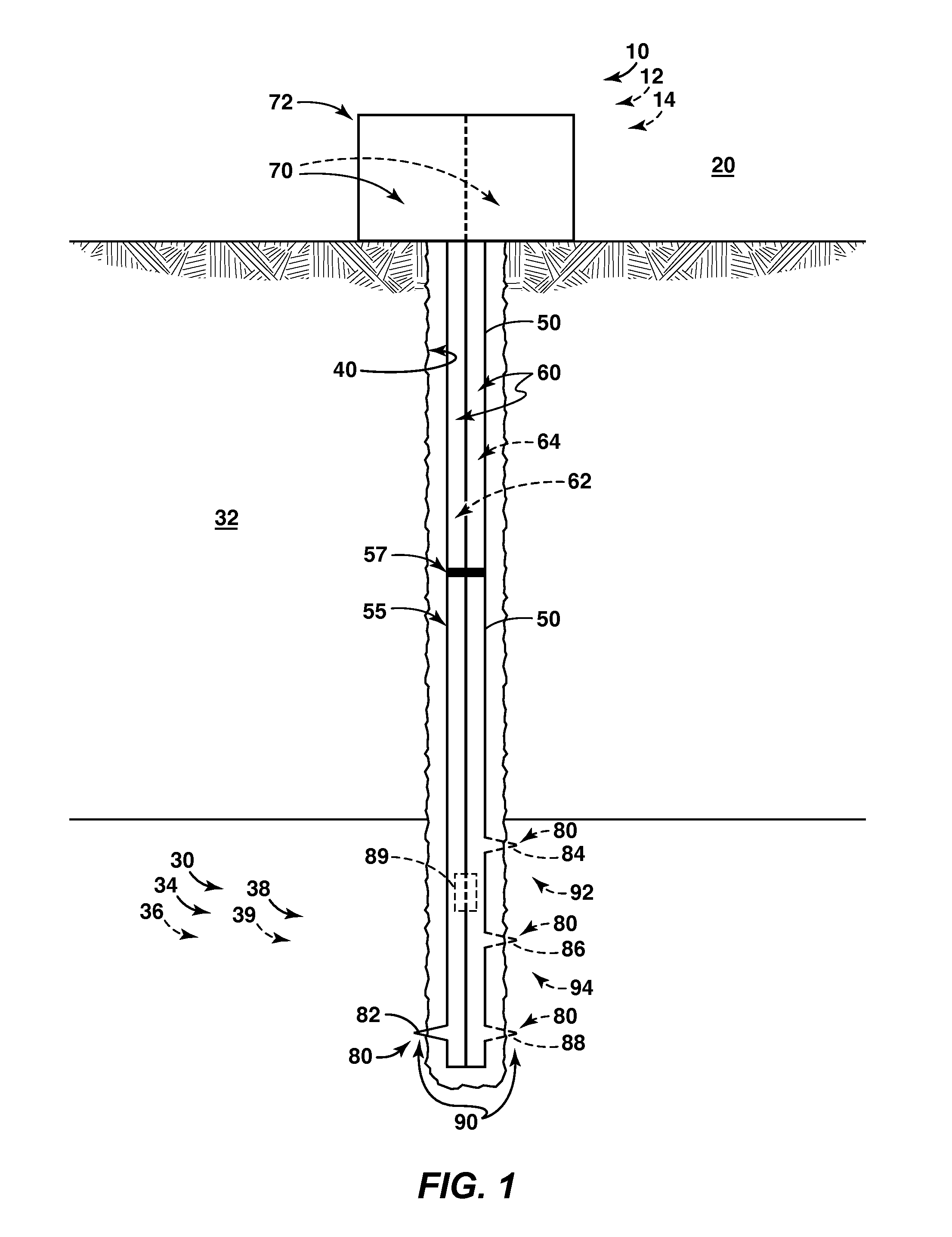
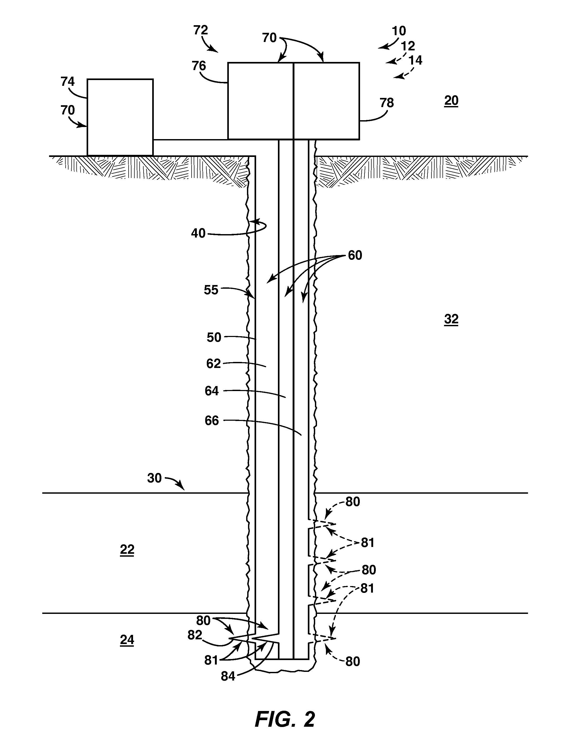
[0027]FIG. 1 provides an illustrative, non-exclusive example of a well 10 according to the present disclosure. The well, which may include a hydrocarbon well 12, an oil well 14, or any other suitable well structure, provides a hydraulic connection between a surface region 20 and a subterranean formation 30 contained within a subsurface region 32. The term “oil well” as used herein is defined broadly to include substantially any well or well that may be useful towards the production of hydrocarbons, such as an oil well, gas well, fluid injection well, monitoring well, exploration well, geothermal well, or other such wellbore. Subterranean formation30 also may be referred to as, and / or as containing or including, a reservoir 34 that contains reservoir fluid 38. When the reservoir fluid includes oil or another hydrocarbon 39, the reservoir may be referred to as an oil reservoir or a hydrocarbon reservoir 36.

[0028]Well 10 includes a wellbore 40 that provides access between the surface r...


PUM


Abstract

Systems and methods for improving functional access to subterranean formations that include a well, which includes a casing string having at least one casing conduit that extends and provides a hydraulic connection between a surface region and the subterranean formation. Performing a plurality of downhole operations utilizing a casing string that constitutes a plurality of hydraulic pathways between the surface region and the subterranean formation. In some embodiments, the plurality of downhole operations may be simultaneous operations and / or may be associated with at least one of a plurality of operational states including a drilling state, completing state, stimulating state, producing state, abandoning state, and / or killing state. In some embodiments, systems and methods may include a plurality of production control assemblies to control and / or monitor the downhole operations.

Description

CROSS REFERENCE TO RELATED APPLICATIONS[0001]This application claims the benefit of U.S. Provisional Application 61 / 438,099, filed Jan. 31, 2011.FIELD OF THE DISCLOSURE[0002]The present disclosure is related generally to systems and methods for improving well access to subterranean formations, and more particularly to such systems and methods that include a plurality of fluid communication pathways between a surface region and a subterranean formation as part of a single, or self-contained, casing conduit.BACKGROUND OF THE DISCLOSURE[0003]In general, a well is a structure that provides access, or communication, between a surface region and a subterranean formation. Illustrative, non-exclusive examples of access may include fluid access or fluid communication (or similarly hydraulic access or hydraulic communication), mechanical access or mechanical communication, data access or data communication, electrical access or electrical communication, and / or any suitable combination of thes...

Claims


Application Information

Patent Timeline
Patent Type & Authority Applications(United States)
IPC IPC(8): E21B17/18E21B47/00E21B21/00E21B43/12E21B34/06
CPCE21B17/18E21B43/12E21B34/06E21B21/00E21B47/00E21B21/12E21B21/08
Inventor DALE, BRUCE A.ENTCHEV, PAVLIN B.KELLER, STUART R.
Owner EXXONMOBIL UPSTREAM RES CO
Learn More