
Optical system, in particular lidar system, and vehicle

a lidar system and optical system technology, applied in the field of optical systems, can solve the problems of power supply and data transfer to the rotating element, the effect of reducing the effective transmission and detector surface area

Pending Publication Date: 2022-01-13
ROBERT BOSCH GMBH
View PDF0 Cites 0 Cited by
  • Summary
  • Abstract
  • Description
  • Claims
  • Application Information

AI Technical Summary

Benefits of technology

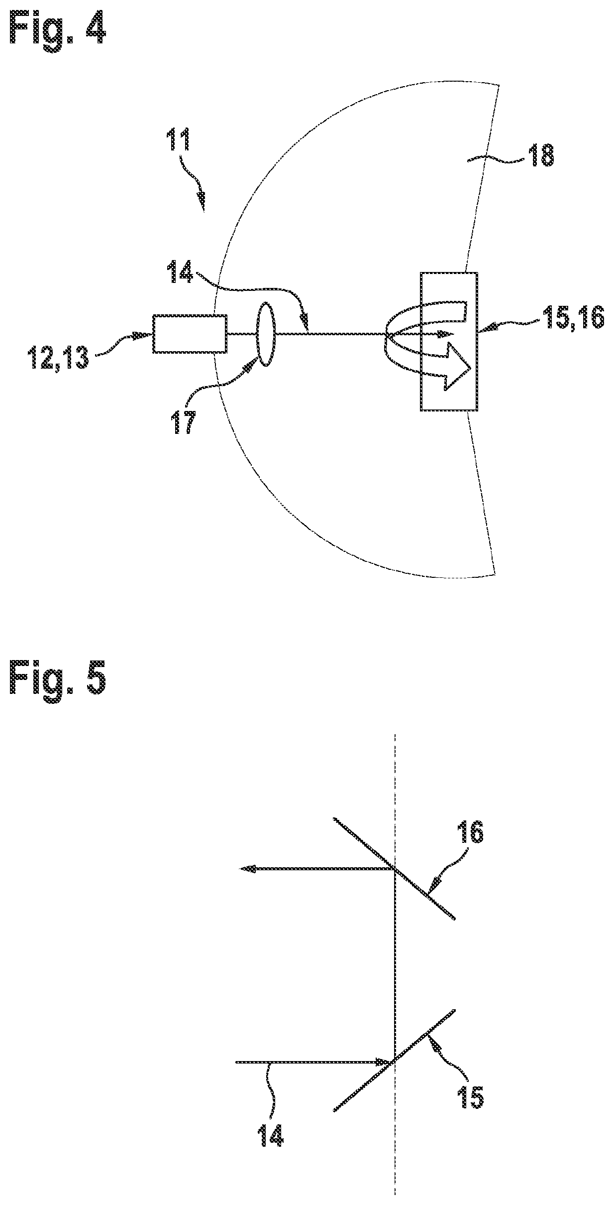
The present invention relates to a device that scans a light beam in a system using two mirror surfaces. The design prevents tilting of the light beam during rotation of the mirror surfaces, allowing for a larger field of view (FoV). The scanning light beam is generated using a beamformer, and the mirror surfaces have a curved shape to simplify the design and improve accuracy. In one embodiment, the optical transmitter and detector are placed on a stator, and the first and second beam paths are superimposed, making it easier to shape the scanning light beam and save on components. The line profile of the scanning light beam is not rotated about its propagation direction, resulting in a more uniform scanning result over the FoV.

Problems solved by technology

However, it turned out to be difficult to achieve a large field of view (FoV) of the optical system without using multiple optical transmitters and optical detectors.
This has the disadvantage that a power supply and a data transfer to the rotating element must be implemented.
The disadvantage of this variant is that for fairly large beam deflection angles, the effective transmission and detector surface area become smaller due to the effective mirror surface area decreasing.
As a result, the angular spans of the achievable horizontal FoV are limited, and the resolution and accuracy of the system become increasingly poorer for larger deflection angles.
However, when multiple pixels are emitted at different angles or in a laser line, the following disadvantage results: If the laser beam, already formed as a laser line, strikes the deflection optical system at an angle of approximately 45°, line illumination cannot be achieved without rotating the line orientation over large solid angles, since for a larger angle, a vertically oriented line is tilted in the direction of a horizontal line.
However, in most applications this is not desirable and would impair the accuracy of the system as a function of the angle.

Method used


Image

  • Optical system, in particular lidar system, and vehicle
  • Optical system, in particular lidar system, and vehicle
  • Optical system, in particular lidar system, and vehicle

Examples


Embodiment Construction

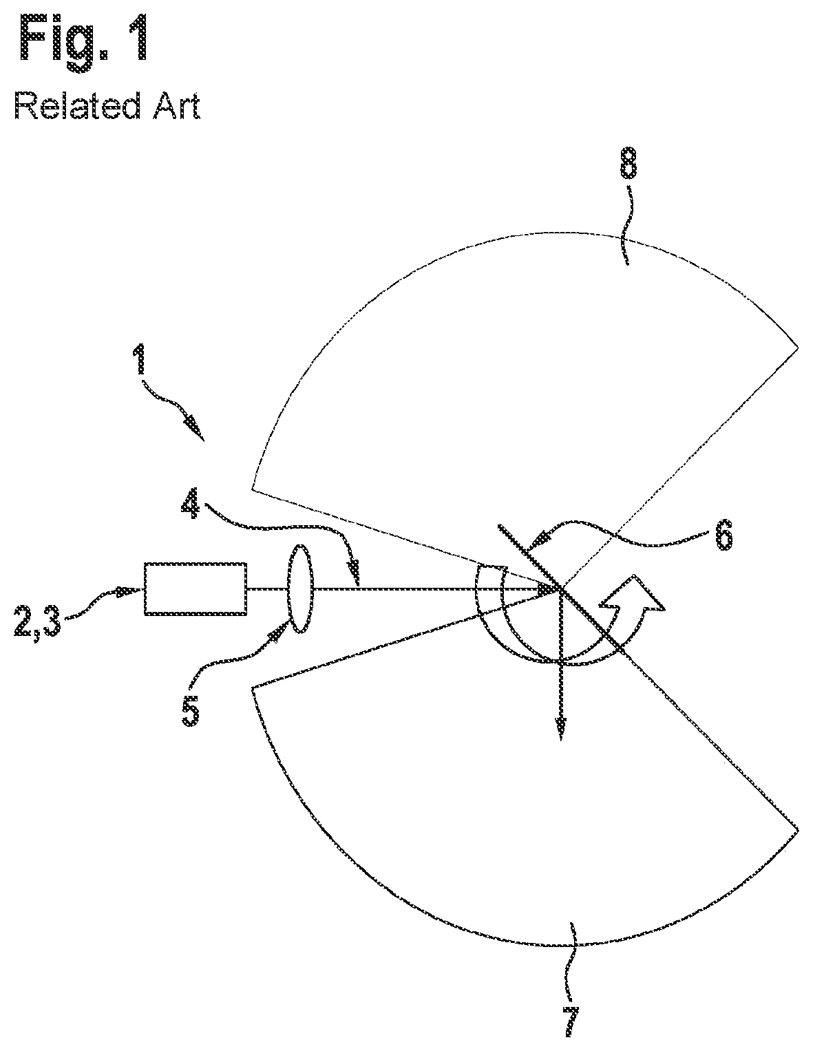
[0035]FIG. 1 shows an optical system 1 of the related art, which includes an optical transmitter 2 and an optical detector 3 that are accommodated in a shared housing. Optical transmitter 2 is configured to emit a scanning light beam into the surroundings along a first beam path 4. An optical element 5 for beamforming is situated in the beam path. The scanning light beam subsequently strikes a mirror surface 6, which deflects the light beam in order to scan the surroundings. The optical system includes two separate FoVs of 140° each, for example, situated to the right and left of a blind spot about a deflection angle of 0°. For this reason, often only one of the two FoVs is used, which greatly limits the functionality of the optical system.

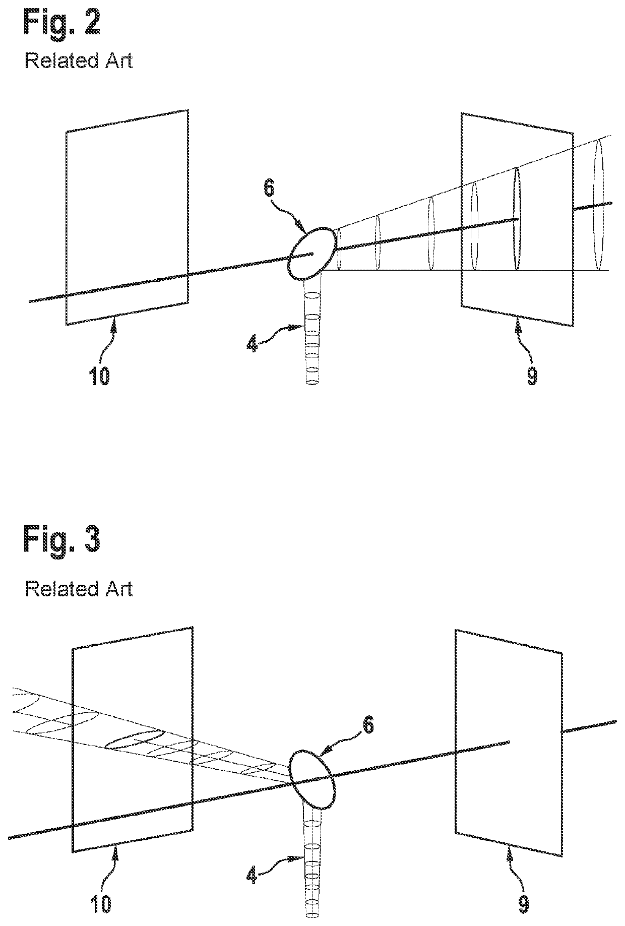
[0036]FIGS. 2 and 3 illustrate a further problem of the related art. Here, in comparison to FIG. 1, only beam path 4 and mirror surface 6 are illustrated for the sake of simplicity, as well as two screens 9, 10 that clarify the form of the scannin...


PUM


Abstract

An optical system includes an optical transmitter which emits a scanning light beam into the surroundings along a first beam path, and an optical detector which receives a reflected light beam from the surroundings along a second beam path. In at least one of the first beam path and the second beam path, two mirror surfaces tilted relative to one another by 90° deflect the light beam from a first plane into a second, parallel plane. The mirror surfaces are rotatably supported and coupled to one another so that when the mirror surfaces are rotated together about a rotational axis perpendicular to the planes, scanning of the surroundings takes place so that no tilting of the light beam occurs during the rotation. Beamforming of the scanning light beam takes place, at least partially, via a curvature of the two mirror surfaces and / or via a beamformer in the first beam path.

Description

FIELD[0001]The present invention relates to an optical system, in particular a LIDAR system, including at least one optical transmitter and at least one optical detector, the optical transmitter being configured to emit a scanning light beam into the surroundings along a first beam path, and the optical detector being configured to receive a reflected light beam from the surroundings along a second beam path, in at least one of the first beam path and the second beam path, mirror surfaces that are tilted relative to one another by 90° deflecting the light beam from a first plane into a second plane parallel thereto.BACKGROUND INFORMATION[0002]Optical systems such as light detection and ranging (LIDAR) systems in particular are used, among other things, as radar-related methods for optical distance and velocity measurement. However, in contrast to radar, objects that are much smaller and closer may be measured with greater accuracy, as the result of which the technology has gained in...

Claims


Application Information

Patent Timeline
IPC IPC(8): G01S17/931G01S7/481B60W40/02
CPCG01S17/931B60W2420/52B60W40/02G01S7/4817G01S7/4812G01S17/42B60W2420/408
Inventor SPIESSBERGER, STEFAN
Owner ROBERT BOSCH GMBH
Learn More