Cosmetic container having touch member to which cosmetic material is transferred by means of pressurized air

Active Publication Date: 2022-01-20
WORLD SPONGE MFG CO LTD
View PDF0 Cites 1 Cited by
  • Summary
  • Abstract
  • Description
  • Claims
  • Application Information

AI Technical Summary

Benefits of technology

[0023]The cosmetic container having a touch member to which a cosmetic material is transferred by means of pressurized air according to the present invention has the following effects:
[0024]First, the cosmetic container has the effect of effectively transferring a cosmetic material to the touch member by using pressurized air generated by pumping the pressure member such as a bellows structure.
[0025]Second, the cosmetic container has the effect to allow an agglomerate cosmetic material to collide and be partially crushed by means of the flow of pressurized air while the pressurized air exiting from the air discharge through hole of the supply part flows into th

Problems solved by technology

The cosmetic container is inconvenient in that a user needs to transfer the cosmetic material to the touch part by shaking the container.
In addition, in the case of a powder cosmetic material such as a

Method used


Image

  • Cosmetic container having touch member to which cosmetic material is transferred by means of pressurized air
  • Cosmetic container having touch member to which cosmetic material is transferred by means of pressurized air
  • Cosmetic container having touch member to which cosmetic material is transferred by means of pressurized air

Examples


first embodiment

[0047]the present invention will be described below with reference to the drawings.

[0048]The structure and operation of the present invention will be described based on the upward, downward, leftward and rightward directions shown in the drawings. However, the structure and the operation are not limited to the directions shown in the drawings.

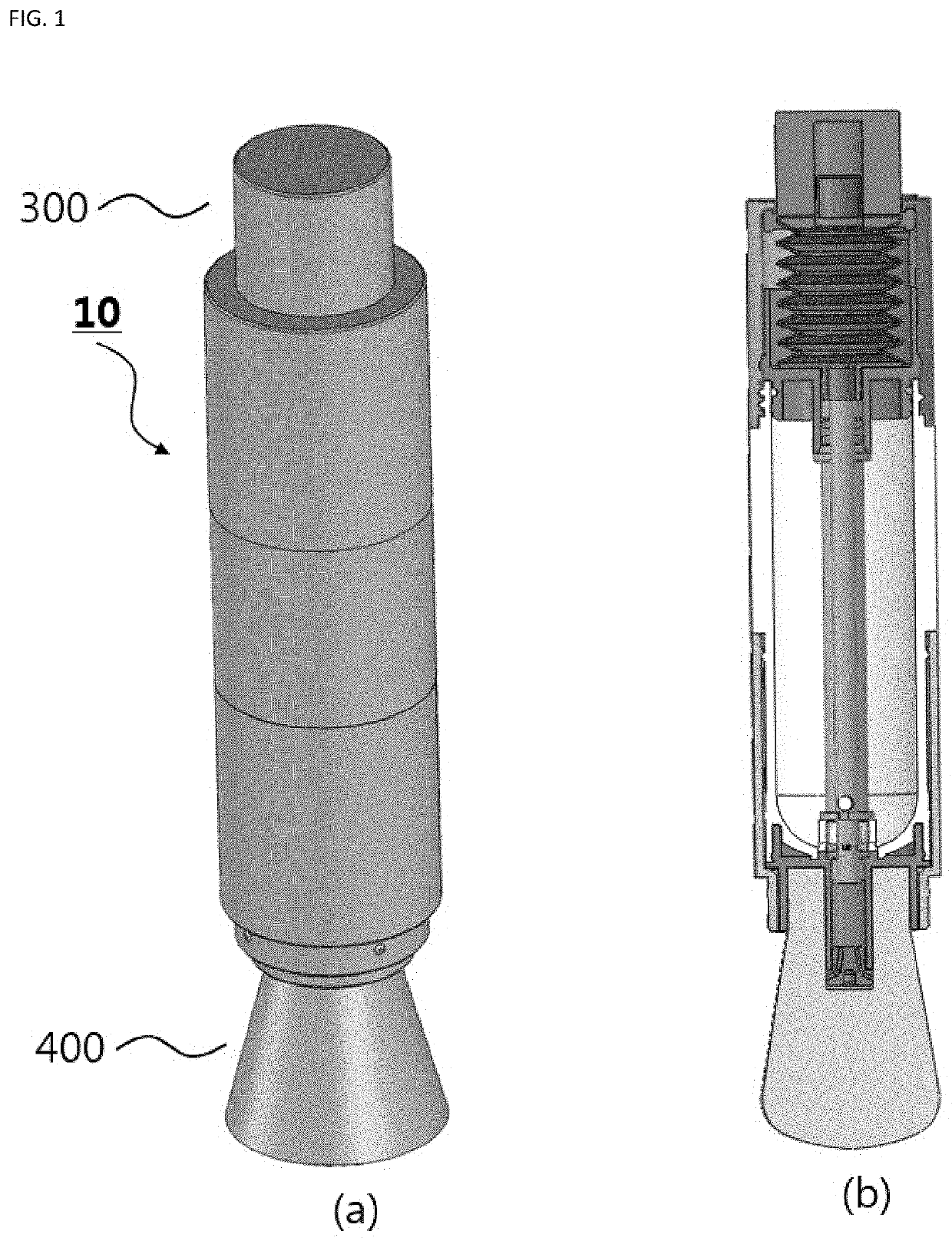
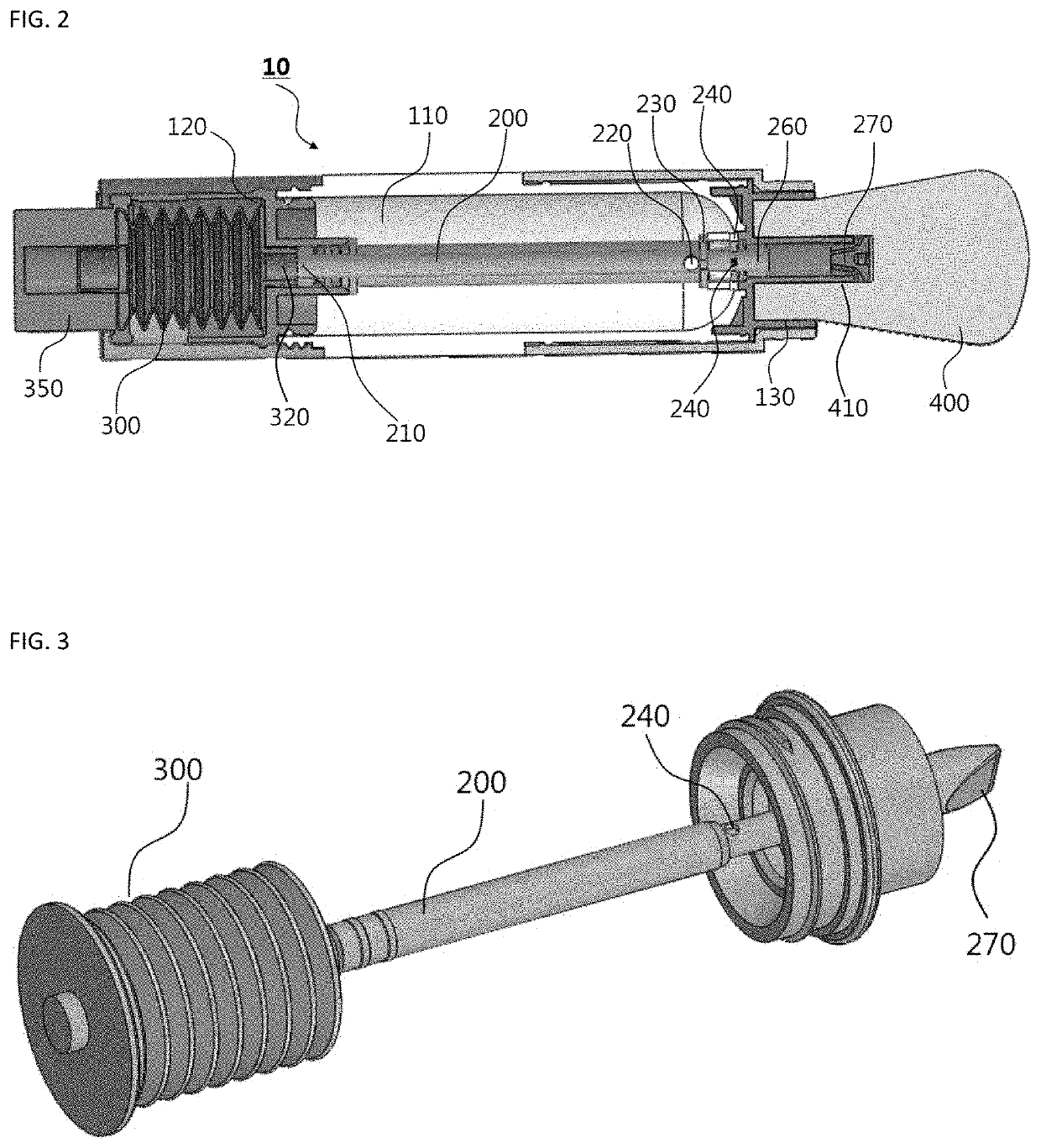
[0049]FIG. 1a is a perspective view of a cosmetic container according to the present invention, and FIG. 1b is a longitudinal sectional view of FIG. 1a. FIG. 2 is a view of the analysis of FIG. 1b.

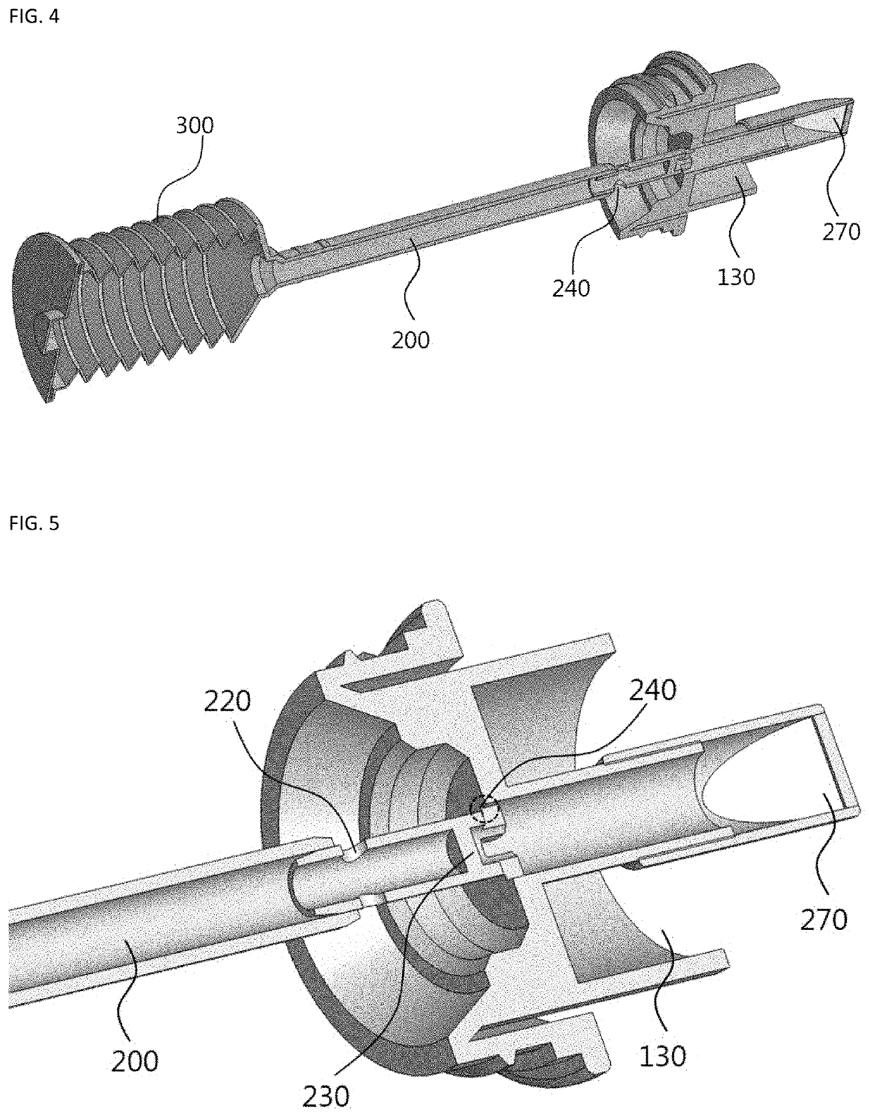
[0050]The cosmetic container according to the present invention is a cosmetic container having a touch member to which a cosmetic material is transferred by means of pressurized air, and includes a body part 100, a supply part 200, a pressure member 300, and a touch member 400.

[0051]The body part 100 according to the present invention has an empty hollow shape, and a cosmetic material accommodation portion 110 may be provided in the body part 100.

[00...

second embodiment

[0097]Accordingly, descriptions of redundant components will be omitted, and the second embodiment will be described with a focus on differences in configuration.

[0098]FIGS. 11 and 12 show another embodiment of the present invention, which is an embodiment without an inner partition inside a supply pipe.

[0099]As shown in FIG. 11, a plurality of cosmetic material introduction holes 240 are formed in a supply pipe 200 according to the present invention. This embodiment has a structure without a partition therein.

[0100]In this embodiment, when pressurized air is injected into the supply pipe 200, it will be moved along the supply pipe 200. Since there is no partition, it will be moved directly up to a spray nozzle 270 (see FIG. 12a).

[0101]When the pressurized air moves at a high speed, a cosmetic material X in the form of a powder accommodated in the cosmetic material accommodation portion 110 is introduced into a supply pipe 200 through introduction through holes 240 formed in the sup...


PUM


Abstract

Disclosed herein is a cosmetic container including: a body part having an empty hollow shape, and provided with a cosmetic material accommodation portion therein; a supply part disposed to pass through the material accommodation portion of the body part, provided in a hollow tube shape, and configured such that an air discharge through hole is formed on one side of a partition disposed inside a hollow tube and a material introduction through hole is formed on the other side of the partition; a pressure member coupled to communicate with the entrance of the supply part at one end of the body part, and configured to inject air into the supply part; and a touch member coupled to communicate with the exit of the supply part at the other end of the body part, and configured such that a cosmetic material introduced through the material introduction through hole is transferred thereto.

Description

TECHNICAL FIELD[0001]The present invention relates to a cosmetic container to which a touch member is coupled. More specifically, the present invention relates to a cosmetic container having a touch member to which a cosmetic material is transferred by means of pressurized air.BACKGROUND ART[0002]There have been cosmetic containers including a structure in which a cosmetic material is transferred to a touch member such as a brush, a puff, or a sponge. As an example of the prior art, there is Korean Patent No. 10-0841441 entitled ‘Cosmetic Container with Dispersion Part.’ This prior art is merely a combination of a cosmetic material and a touch part, which are separately provided, in the same container.[0003]The cosmetic container is inconvenient in that a user needs to transfer the cosmetic material to the touch part by shaking the container. In addition, in the case of a powder cosmetic material such as a powder, it has the property of being lumped and tangled. When such a cosmetic...

Claims


Application Information

Patent Timeline
IPC IPC(8): A45D33/02A45D33/34A45D34/04B65D83/20B65D83/46
CPCA45D33/02A45D33/34A45D34/042A45D2200/1009B65D83/46A45D2200/054B65D83/20B05B11/062B05B11/061A45D2200/057A45D2200/10B65D83/44A45D33/36
Inventor OHN, SUNGDAE
Owner WORLD SPONGE MFG CO LTD
Why Eureka
Try Eureka