Video switching apparatus, video switching method, program, and information processing apparatus

Active Publication Date: 2015-12-31
SONY CORP
View PDF1 Cites 1 Cited by
  • Summary
  • Abstract
  • Description
  • Claims
  • Application Information

AI Technical Summary

Benefits of technology

[0017]According to the first aspect or the second aspect of the present disclosure, video data can be transferred more effici

Problems solved by technology

In the case where transferring video data for broadcast in a broadcasting station or the like by using a best-effort-type communication network, a loss of data or a change of image

Method used


Image

  • Video switching apparatus, video switching method, program, and information processing apparatus
  • Video switching apparatus, video switching method, program, and information processing apparatus
  • Video switching apparatus, video switching method, program, and information processing apparatus

Examples


embodiment

1. EMBODIMENT

[Configuration Example of the Video Processing System]

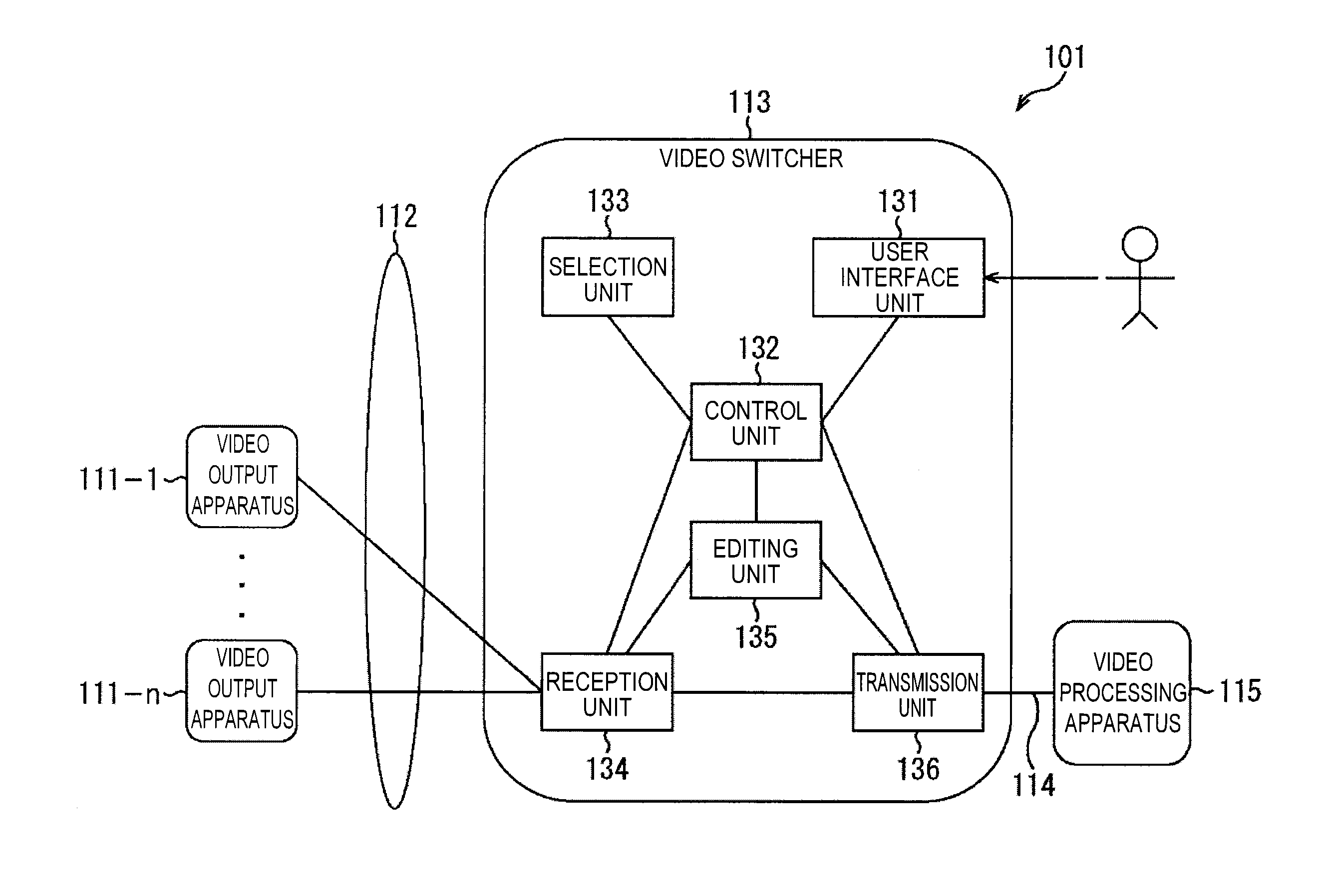
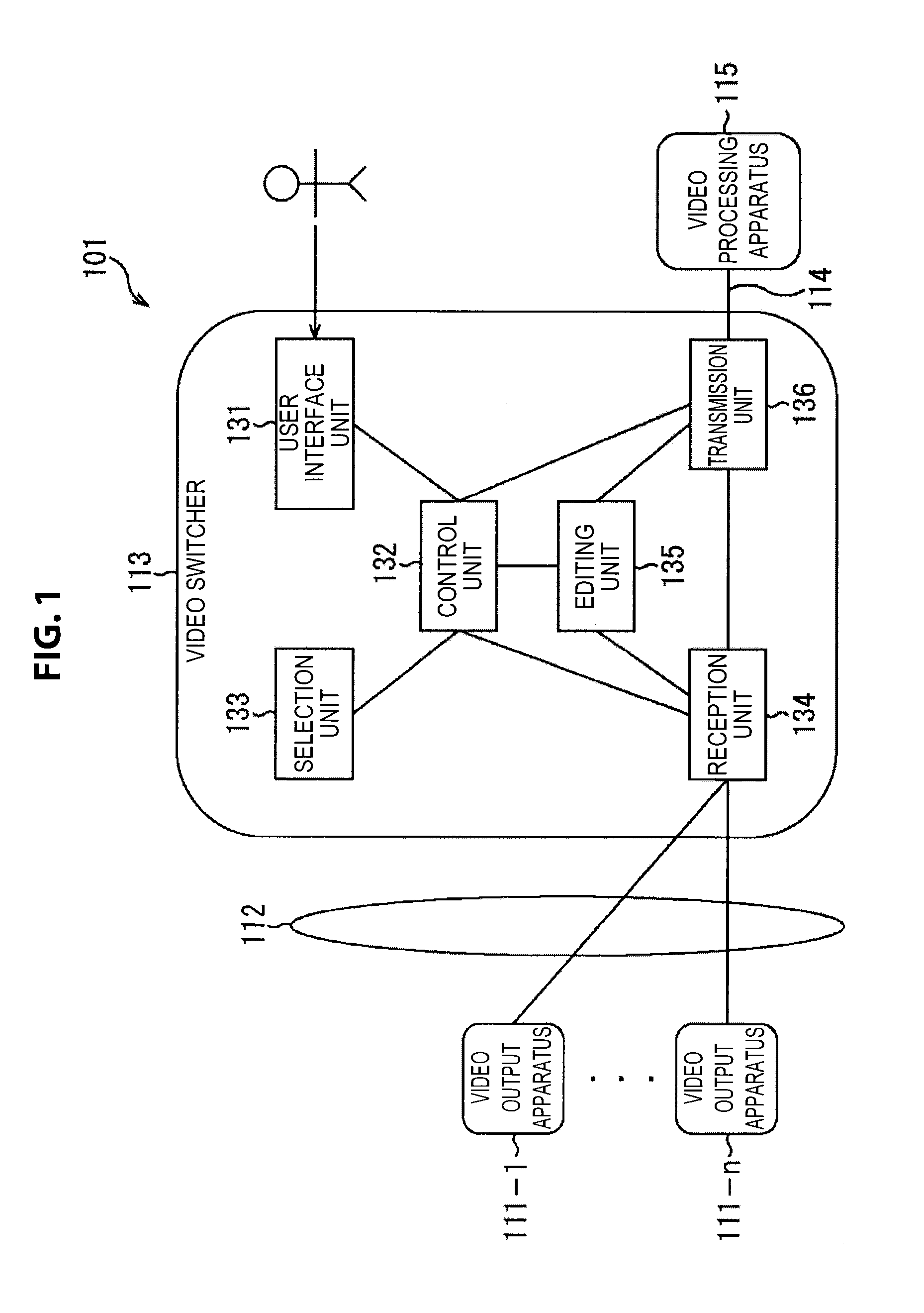
[0039]FIG. 1 shows an embodiment of a video processing system applicable to the present disclosure.

[0040]The video processing system 101 is a system, for example, included in a broadcasting station or the like, which performs various types of processes of video data, for example, the generation, editing, transferring, sending, recording or the like of video data.

[0041]Here, not only a video, but various types of data which accompany a video, for example, audio data, metadata or the like, is included in the video data.

[0042]The video processing system 101 is constituted by including video output apparatuses 111-1 through to 111-n, a network 112, a video switcher 113, a cable 114, and a video processing apparatus 115. The video output apparatuses 111-1 through to 111-n and the video switcher 113 are mutually connected via the network 112. The video switcher 113 and the video processing apparatus 115 are mutually connec...

modified example 1

Modified Example Related to a Selection Method of the Cutting Targets

[0175]In the above described description, while an example has been shown in which the video switcher 113 selects the cutting targets, a user may select the cutting targets from among the cutting candidates.

[0176]FIG. 15 shows a sequence diagram of a video switching process executed by the video processing system 201 in the case where a user selects the selection targets.

[0177]In the case where a switching request has been input from a user, the user interface unit 131 of the video switcher 113 supplies a switching request signal to the control unit 132.

[0178]The control unit 132 supplies a cutting candidate selection request signal to the selection unit 133.

[0179]The selection unit 133 selects the cutting candidates by the above described process, and supplies a response signal for the cutting candidate selection request signal to the control unit 132. The cutting candidate selection request signal includes, for e...

modified example 2

Modified Example Related to the Configuration of the Video Processing System

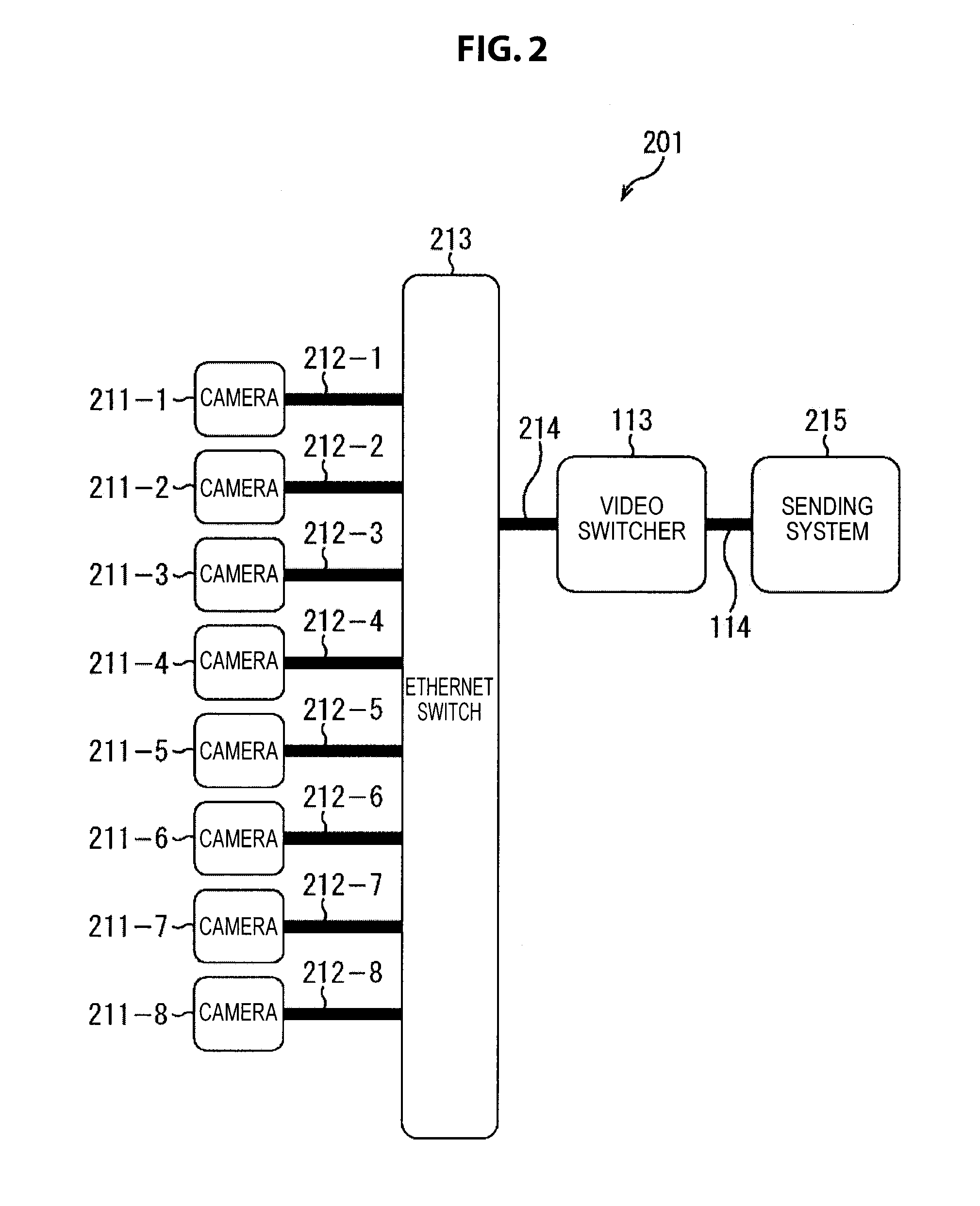
[0190]In the above described description, while an example has been shown which sets the number of the video switchers 113 connected to the network 112 (Ethernet switch 213) to one, it may be connected to two or more. In the case of being connected to two or more, it is possible for each of the video switchers 113 to respectively execute the above described video switching process independently.

[0191]Further, for example, the video switchers may be installed in separate servers or the like, by making a part of the functions of the video switchers (for example, the selection unit 133 or the like) independent, such as shown in FIG. 17.

[0192]Specifically, the video processing system 401 of FIG. 17 is constituted by including cameras 211-1 through to 211-8, cables 212-1 through to 212-8, an Ethernet switch 213, cables 411-1 and 411-2, video switchers 412-1 and 412-2, cables 413-1 and 413-2, a sending system 414,...


PUM


Abstract

A video switcher includes: a reception unit which receives video data within a range of a prescribed bandwidth via a network from video output apparatuses; a transmission unit which selects one or more pieces from among received video data, and transmits the selected one or more pieces to a video processing apparatus; a selection unit which dynamically sets a priority degree of each piece of video data, and selects video data to be received; and a control unit which controls a transmission and reception of video data. When a bandwidth necessary for a reception of new video data is insufficient, the selection unit selects video data for which reception is to be stopped from among video data being received based on the priority degree, and the control unit performs a control so as to stop a reception of selected video data and start a reception of the new video data.

Description

TECHNICAL FIELD[0001]The present disclosure relates to a video switching apparatus, a video switching method, a program and an information processing apparatus, and specifically relates to a video switching apparatus, a video switching method, a program and an information processing apparatus to be suitably used in the case where receiving a plurality of video data via a network, and switching video data to be transmitted in a later stage from among the received plurality of video data.BACKGROUND ART[0002]In the case where transferring video data for broadcast in a broadcasting station or the like by using a best-effort-type communication network, a loss of data or a change of image quality will not be permitted, and so a method will not able to be adopted which dynamically changes an encoding rate of the video data, in accordance with traffic of the network. Therefore, it may be necessary to control a transfer amount of the video data, so that a usage band of the video data to be t...

Claims


Application Information

Patent Timeline
IPC IPC(8): H04N5/268H04L47/2416
CPCH04N21/23439H04N21/2662H04H20/42H04N5/268H04N21/2187H04N21/2393H04N21/2402H04N21/2665H04H20/10H04H60/04H04N5/247H04N5/38H04N5/44H04N21/24H04N23/90
Inventor MASUDA, YASUTO
Owner SONY CORP
Why Eureka
Try Eureka