Transferring roller, transfer device, and image forming apparatus

Inactive Publication Date: 2006-03-28
CANON KK
View PDF10 Cites 0 Cited by
  • Summary
  • Abstract
  • Description
  • Claims
  • Application Information

AI Technical Summary

Benefits of technology

[0016]An object of the present invention is to provide an image forming apparatus, a transfer device and a transferring roller in which it is possibl

Problems solved by technology

Transferring belt type image forming apparatuses require a process in which, in the case of four-full-color image forming, transfer to an object such as a transfer material (e.g., paper or a transparent resin film) or a transferring belt having an instability factor with respect to the resistance value is performed four times and therefore have the disadvantage of being not sufficiently stable with respect to the kind of transfer material and conditions in environments where they are installed.
If the transferring voltage is excessively high, excessive discharge or abnormal discharge occurs between the members, to which the high voltage is applied, resulting in failure to suitably transfer toner.
In particular, if a leak site or the like exists between the transfer member and the transferring belt, dischar

Method used


Image

  • Transferring roller, transfer device, and image forming apparatus
  • Transferring roller, transfer device, and image forming apparatus
  • Transferring roller, transfer device, and image forming apparatus

Examples


first embodiment

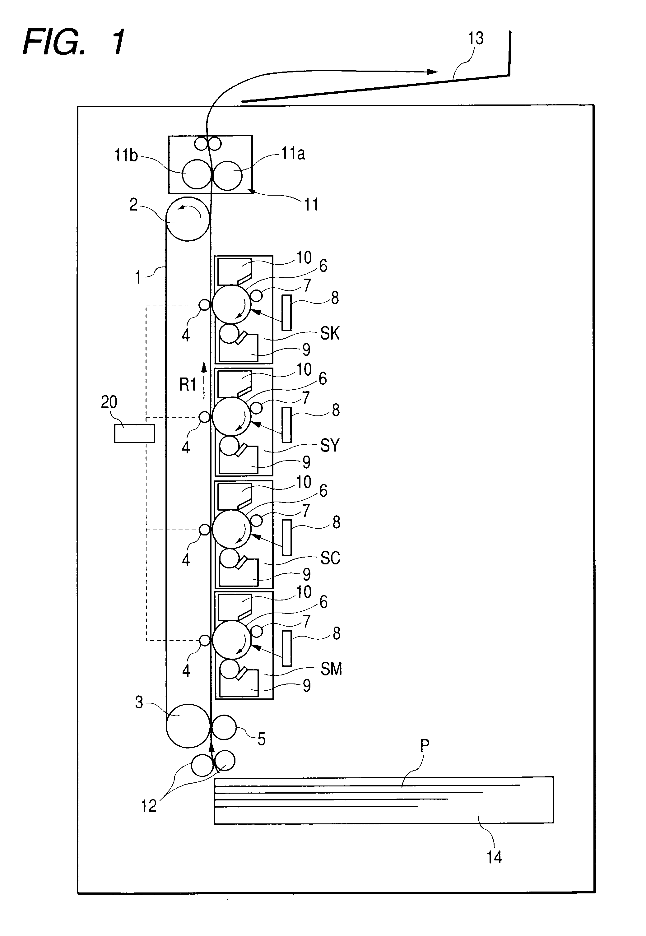
[0033]FIG. 1 shows an example of an image forming apparatus according to the present invention. The image forming apparatus shown in FIG. 1 is a four-full-color laser printer based on an electrophotographic system and having four image forming stations for forming toner images in different colors. FIG. 1 is a longitudinal sectional view schematically showing the construction of this laser printer.

[0034]The schematic construction of the laser printer (hereinafter referred to as “image forming apparatus”) will be described with reference to FIG. 1.

[0035]The image forming apparatus shown in FIG. 1 has an endless transferring belt 1 provided as a transferring and conveying member. The transferring belt 1 is stretched between a drive roller 2 and a driven roller 3. With the rotation of the drive roller 2 in the direction of an arrow indicated in the figure, the transferring belt 1 moves in the direction of arrow R1.

[0036]A sheet-feeding cassette 14 in which a transfer material (recording...

second embodiment

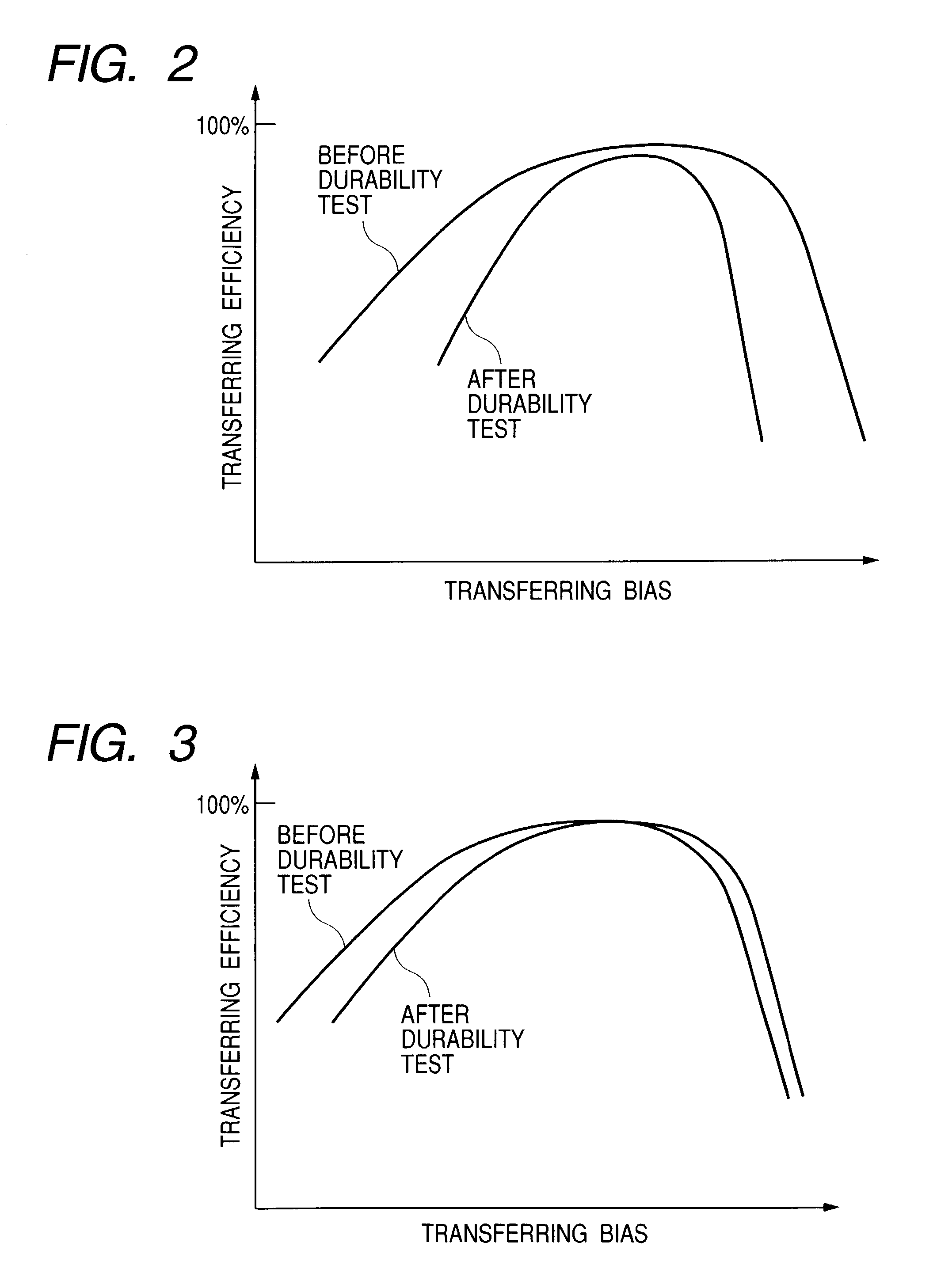
[0064]In this embodiment, in a case of an in-line system image forming apparatus using a transferring belt, an ion-conductive transfer member having a surface not smooth, e.g., a surface in sponge form is used to prevent occurrence of an image defect when a high transferring voltage is applied. Also, an antioxidant is blended in the material forming the transfer member to enable the desired performance to be maintained during a durability test. The construction of the image forming apparatus of this embodiment is the same as that of Embodiment 1 (shown in FIG. 1). The image forming apparatus of this embodiment has an OHT mode which is selected when image forming is performed on an OHT sheet.

[0065]As described above in the description of Embodiment 1, in a system using the transferring belt 1 in an in-line system image forming apparatus, there is a need to set the transferring voltage from an image forming station at a downstream position to a higher value because of charge-up in the...


PUM


Abstract

An image forming apparatus includes an image bearing member, and a transfer member, wherein an image on the image bearing member is transferred to a member to be transferred by applying a voltage to the transfer member, and wherein the transfer member has an ion conductor part having an antioxidant. Variation in resistivity accompanying a change in applied voltage is thereby reduced, whereby sufficiently high transferring efficiency can be maintained during a durability test.

Description

BACKGROUND OF THE INVENTION[0001]1. Field of the Invention[0002]The present invention relates to an image forming apparatus such as a printer, a copying machine, or a facsimile machine, and more particularly, to a transfer device (apparatus) and a transfer member used in the image forming apparatus.[0003]2. Related Background Art[0004]In recent years, the development of image forming apparatuses such as printers, copying machines, and facsimile machines capable of operating at higher speed, having an increased number of functions and capable of forming images in an increased number of colors has progressed. Such image forming apparatuses heretofore proposed use various image forming systems. Among them, inline-type image forming apparatuses in which image forming means using a plurality of different colors are arranged in a row to successively transfer toner images directly onto a belt or onto a transfer material born by a transferring belt in a multiple transfer manner such that to...

Claims


Application Information

Patent Timeline
IPC IPC(8): G03G15/20G03G15/16
CPCG03G15/1685G03G2215/0119
Inventor TSURUYA, TAKAAKISAITO, YOSHIROEBIHARA, SHUNICHI
Owner CANON KK
Why Eureka
Try Eureka