
Paint Brush with Integrated Cleaning Mechanism

a cleaning mechanism and paint brush technology, applied in the field of paint brushes, can solve the problems of affecting the cleaning effect of paint brushes, and requiring the disposal of paint brushes, etc., and achieve the effect of thorough and easy cleaning, easy attachment or detachment of the brush head assembly, and thorough and easy cleaning

Inactive Publication Date: 2022-01-27
SUNDQUIST ZANE
View PDF7 Cites 0 Cited by
  • Summary
  • Abstract
  • Description
  • Claims
  • Application Information

AI Technical Summary

Benefits of technology

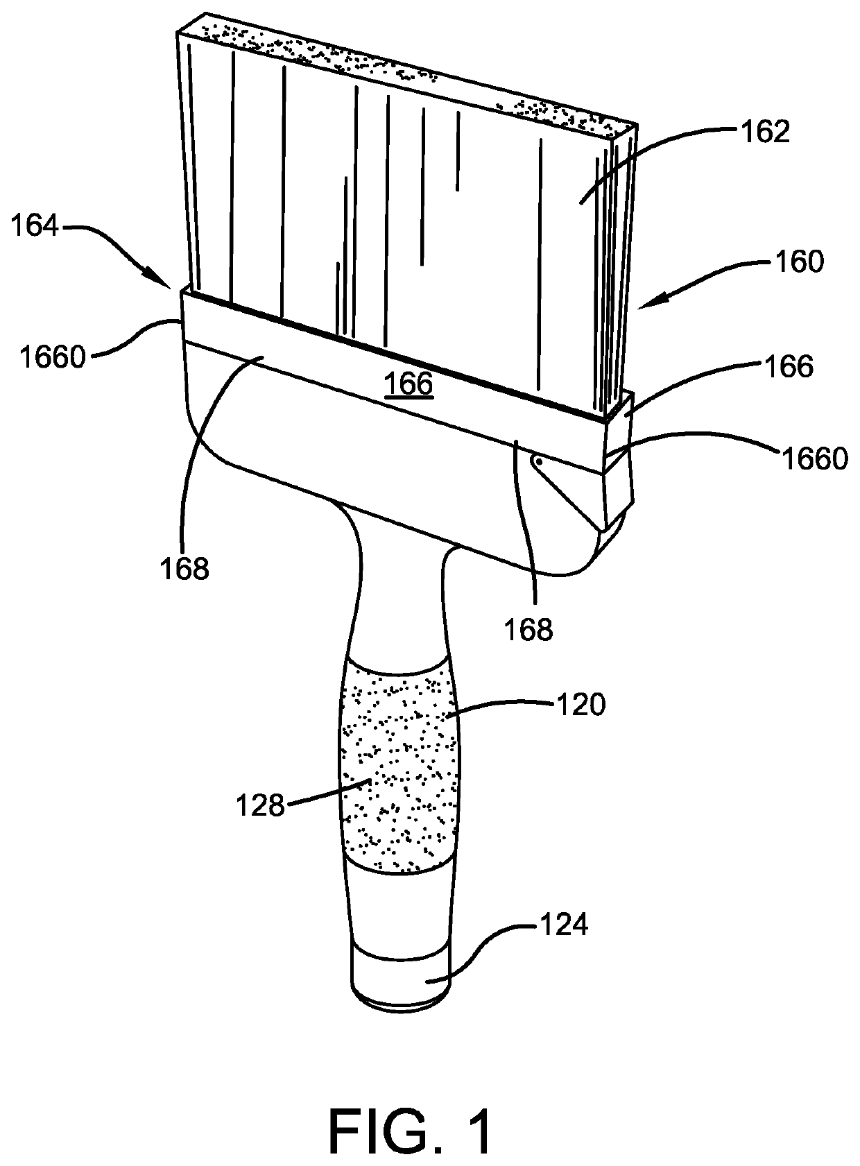
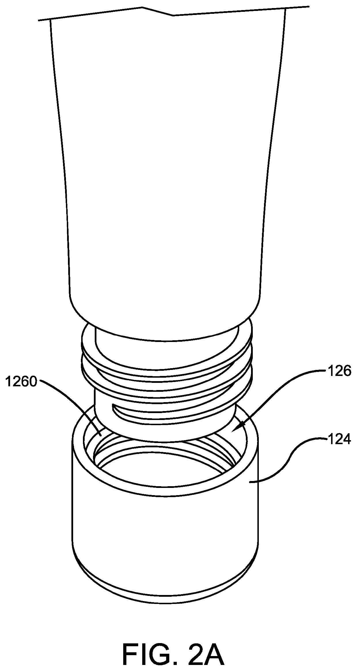
The patent text describes an improved paint brush device that allows for easy cleaning and switching between brush heads. The device includes a brush head assembly with multiple bristles attached to a base, which is secured to the body of the device using a locking member and sidewall. The top surface of the locking member has protrusions that engage grooves within the side surfaces of the base to further secure the brush head assembly to the body. The user can easily detach or discard the brush head without needing to discard the entire device. The design of the brush head assembly, body, and locking member allows for easy cleaning and switching between brush heads.

Problems solved by technology

This dried paint must then be removed from the bristles which is a tedious, physically involved and time-consuming process, especially when the paint has been dry for a long period of time.
Further, if dried paint remains on the bristles of a paintbrush long enough, the paint cannot be removed in an efficient and timely manner, and the entire paintbrush must be discarded, which is obviously economically undesirable for all users.
However, if a user only possesses one or a limited amount of paint brushes, each brush must be cleaned before the brush is used for a different paint color.
Depending on the amount of brushes and the number of paints being used, this repeated cleaning process can also be incredibly time-consuming, burdensome and undesirable.
However, a user can only combat this problem by purchasing more paint brushes, which may not be economically viable for the user.

Method used


Image

  • Paint Brush with Integrated Cleaning Mechanism
  • Paint Brush with Integrated Cleaning Mechanism
  • Paint Brush with Integrated Cleaning Mechanism

Examples


Embodiment Construction

[0022]The innovation is now described with reference to the drawings, wherein like reference numerals are used to refer to like elements throughout. In the following description, for purposes of explanation, numerous specific details are set forth in order to provide a thorough understanding thereof. It may be evident, however, that the innovation can be practiced without these specific details. In other instances, well-known structures and devices are shown in block diagram form in order to facilitate a description thereof. Various embodiments are discussed hereinafter. It should be noted that the figures are described only to facilitate the description of the embodiments. They are not intended as an exhaustive description of the invention and do not limit the scope of the invention. Additionally, an illustrated embodiment need not have all the aspects or advantages shown. Thus, in other embodiments, any of the features described herein from different embodiments may be combined.

[0...


PUM

PropertyMeasurementUnit
of timeaaaaaaaaaa
colorsaaaaaaaaaa
coloraaaaaaaaaa

Abstract

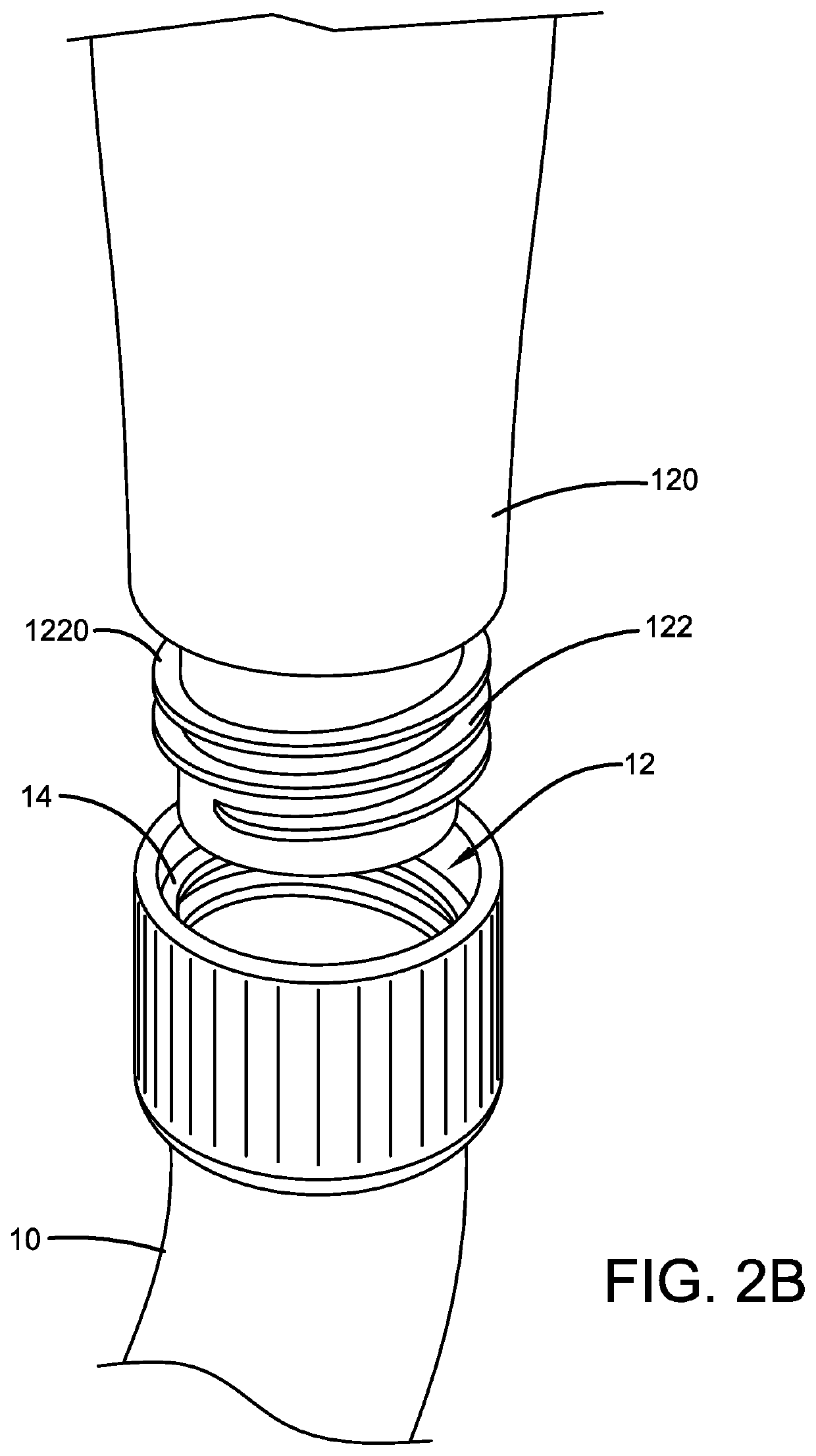
The present invention relates generally to the field of paint brushes. More specifically, the present invention relates to an improved paint brush that is comprised of a hollow body and hollow stem. The stem of the brush can further receive a hose, wherein the hose can allow water to flow through the stem and body, and out of the top surface of the body via a plurality of continuous openings. The top surface also receives a brush head assembly that is comprised of a hollow base and a plurality of bristles. The brush head assembly is further removably secured to the top surface via a sidewall and a locking member that can be engaged or disengaged from a locked position to allow the assembly to be removed from the body for cleaning or replacement.

Description

CROSS-REFERENCE TO RELATED APPLICATION[0001]The present application claims priority to, and the benefit of, U.S. Provisional Application No. 63 / 054,323, which was filed on Jul. 21, 2020 and is incorporated herein by reference in its entirety.FIELD OF THE INVENTION[0002]The present invention relates generally to the field of paint brushes. More specifically, the present invention relates to an improved paint brush that is comprised of a hollow body and a stem. The stem of the brush can further receive a hose, wherein the hose can allow water to flow through the stem and body and out of the top surface of the body via a plurality of continuous openings. The top surface also receives a brush head assembly that is comprised of a hollow base and a plurality of bristles. The brush head assembly is further removably secured to the top surface via a sidewall and a locking member that can be engaged or disengaged from a locked position to allow the assembly to be removed from the body for cl...

Claims


Application Information

Patent Timeline
Patent Type & Authority Applications(United States)
IPC IPC(8): A46B17/06B44D3/00A46B11/06
CPCA46B17/06A46B2200/202A46B11/06B44D3/006
Inventor SUNDQUIST, ZANE
Owner SUNDQUIST ZANE
Learn More