[0014]The figures included serve as examples of some embodiments of the present invention. The present invention is not limited by the figures depicted in the drawings.
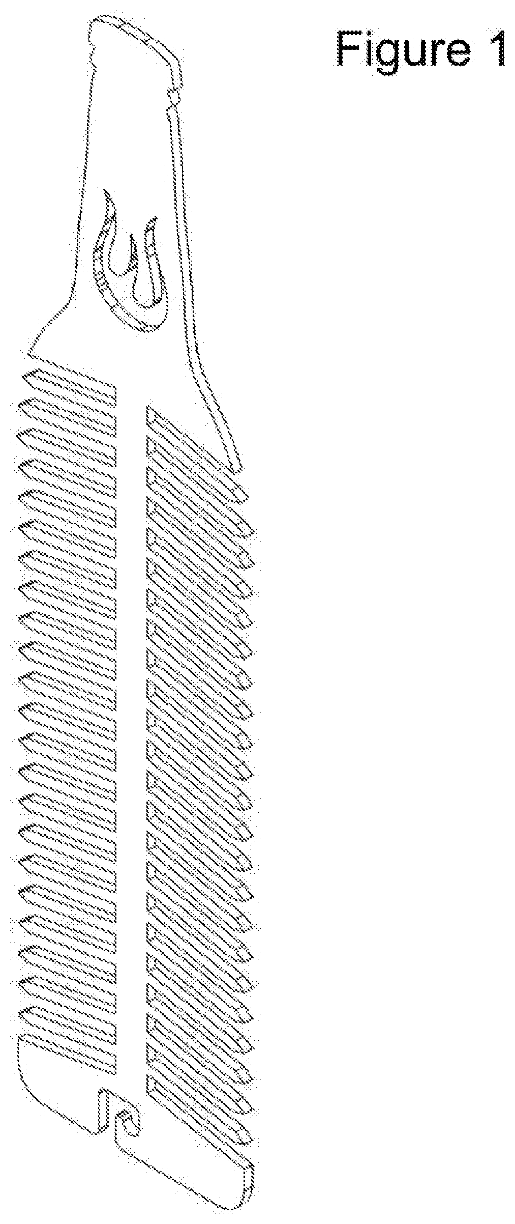
[0015]FIG. 1 depicts an example of an angled side view according to various embodiments of the present invention.
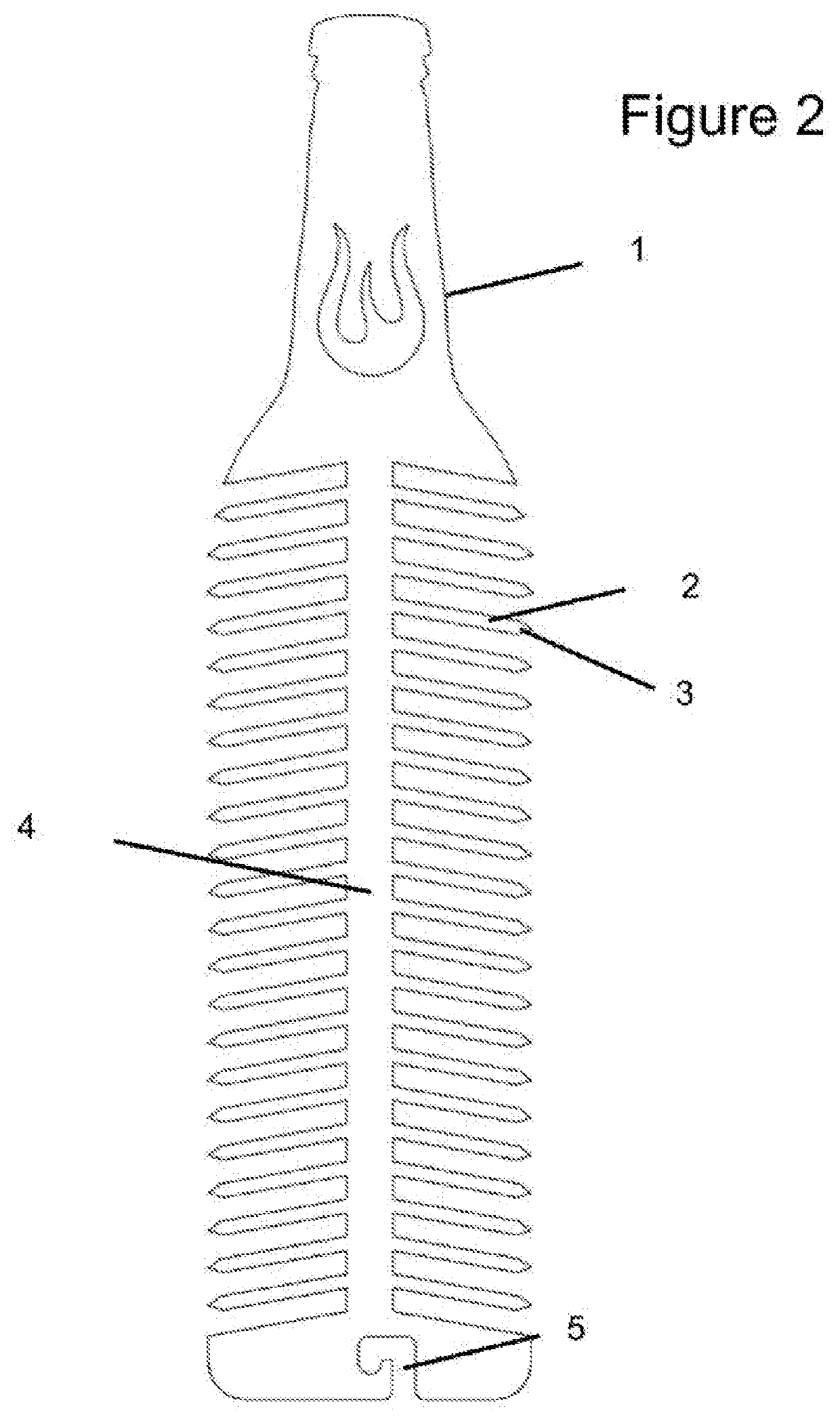
[0016]FIG. 2 depicts an example front view according to various embodiments of the present invention.
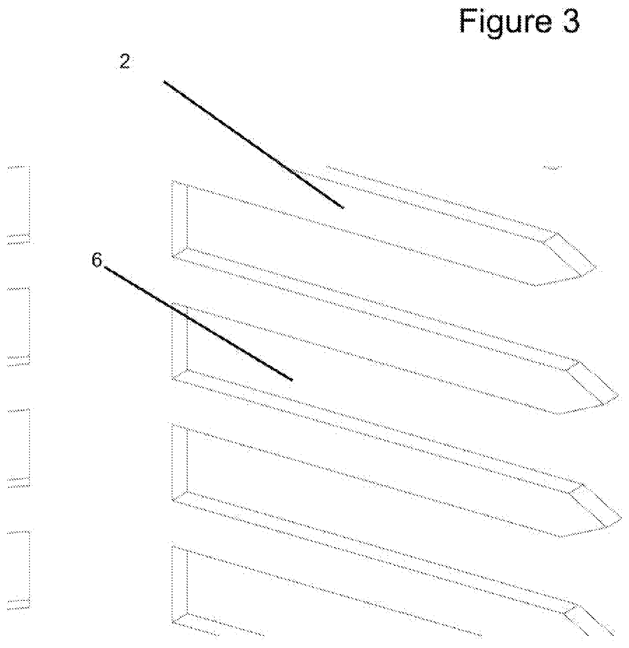
[0017]FIG. 3 depicts an example of a close-up view of the rib-like structure on the present invention according to various embodiments of the present invention.
[0018]FIG. 4 depicts an example of a close-up view of the spoke-like prongs on the present invention according to various embodiments of the present invention.
[0019]FIG. 5 depicts an example of a close-up view of the upper region of the present invention according to various embodiments of the present invention.
DETAILED DESCRIPTION
[0020]The terminology used herein is for the purpose of describing different embodiments only and is not intended to limit the invention. The words “and/or” include all combinations of one or more of the associated listed items. As used herein, the singular forms “a,”“an,” and “the” are meant to incorporate the plural forms and the singular forms, unless stated otherwise. Also, the words “comprises” and/or “comprising,” specify the presence of the stated elements, but do not exclude other elements not stated. Unless otherwise defined, all terms used herein have the same meaning as usually understood by one having ordinary skill in the art to which this invention belongs.
[0021]In describing the invention, the steps and techniques are disclosed. Each of these steps and techniques have individual benefits but can also be used with one or more, or in some cases all, of the other steps and techniques acknowledged. For the sake of clarity, this description will not repeat every possible combination of the individual steps unnecessarily. However, it must be understood that such combinations are entirely within the scope of the invention and the claims.
[0022]New skewering devices are discussed herein. For the purpose of explanation, in the following description multiple details are expressed in order to provide an accurate perception of the present invention. It will be clear, however, to one skilled in the art that the present invention may be used without these specific details. The present disclosure is to be considered as an example of the invention and is not intended to limit the invention to the specific embodiments described below. The present invention will now be discussed and explained further by referencing the attached images below. For the sake of brevity, the present invention may be referred to as “the device” in some places throughout the rest of the description.
[0023]FIG. 1 illustrates an angled side view perspective of the preferred embodiment. The preferred embodiment is made out of 2.5 mm thick stainless steel but can also be made of, but not limited to: steel, aluminum or other suitable metals or materials. The preferred embodiment is cut out of sheet metal however other processes can be used to acquire the desired shape such as, but not limited to die casting, milling, or any other metal or material fabrication method. The device has a total length of about 300 mm however it is not limited to this length only. Being made out of stainless steel allows the device to keep its strength and form after repeated heating and cooling cycles. The device material thickness of 2.5 mm makes it so that the device will not bend, twist, or deform during use but will still provide adequate strength and support. The material choice also allows heat conduction to occur throughout the device.
[0024]FIG. 2 illustrates what one prong 2 of the device looks like. It is a rectangular body with a pointed tip 3 however it is not limited to this shape. Alternative embodiments could include rounded rectangles, ovals, or any other shape used to create a prong-like piece. In alternative embodiments, the pointed tip 3 may also be a different shape or not be pointed at all.
[0025]The preferred embodiment has 3 mm wide prongs 2 spaced evenly at 5 mm apart along the length of the center metal strip. The prongs 2 are about 30 mm long (with some potentially shorter) to match the bottle design shape. The prongs 2 are tilted towards the hook 5 structure at an angle of 10 degrees from the horizontal position. The above measurements are simply for the preferred embodiment but are not only limited to these. A combination of other prong lengths, widths, and spacings can be used to create an alternative embodiment.
[0026]FIG. 2 illustrates what the center heat channel strip 4 looks like. It is rectangular in shape and is approximately 10 mm in width and approximately 184 mm in length in the preferred embodiment. Like the rest of the device, the center heat channel strip 4 (‘the center strip’) is 2.5 mm thick in the preferred embodiment. These are only dimensions for the preferred embodiment and alternative embodiments may include a range of different dimensions and shapes. The center strip 4 acts as a connector for the prongs 2. The prongs 2 are connected on the sides of the center strip 4. The center strip's length allows it to hold the total number of prongs 2 required. In the preferred embodiment, the center strip 4 holds twenty-two prongs 2 on each side and are evenly spaced along the center strip 4. Alternative embodiments may include more or less no or prongs 2 with even or uneven spacing between them.
[0027]Currently, a food item will be placed onto the device by being skewered onto a plurality of prongs 2. These prongs 2 piercing a single food item will improve heat distribution since the center strip 4 acts as a heat channel. When the device is heated, the center strip 4 is heated as well. The center strip's width allows it to transfer heat efficiently to the prongs 2 and eventually to the center of the food items. This allows for the even distribution of heat inside the food item as there are a plurality of prongs 2 buried within each food item. This prevents food from being overcooked on the outside while being undercooked or uncooked on the inside. Also, because there is a plurality of heat distribution points inside the food, food items will cook faster which in turn saves user's time and energy from the heat source.
[0028]In addition, the width and spacing of the prongs 2 allows a plurality of prongs 2 to pierce a single piece of food. This forces the food item to be held in place and prevents sliding even if the device is moving. The plurality of points of contact create stability. The food items staying in place and not touching other food items results in a higher quality of cooking. If different food items touch each other, they may exchange flavors and ruin the quality. In addition, food that is apart from each other ensures that the heat can surround the entire piece and can cook each food piece thoroughly.
[0029]Another reason for the prong 2 width and spacing is to accommodate all types of food item sizes. Since the prongs 2 are close together, many different sized food items can be attached. The prong 2 placement on the device allows for the user to observe how large their food item is and choose the correct number of prongs 2 to fully fit the food piece onto the device. Varying the food item size will result in more or less prongs 2 being used by a single item.
[0030]In addition, the width and spacing between the prongs 2 also allows for easily removing food items once they are cooked from the device. FIG. 3 shows the prongs 2 and the gaps 6 between them. Since the 3 mm wide prongs 2 can fit in the 5 mm wide gaps 6 between prongs 2, two devices can be used together to remove food items off of each other. Interlocking two devices and then sliding one across the prongs 2 of the other will remove the food items. This is designed so users do not have to get their hands dirty or contaminate the food with their hands while removing the food items. This design also allows for the easy cleaning of the device. The device can easily be cleaned by interlocking two devices and then moving them in a back and forth motion to clean off any remaining food debris.
[0031]As shown in FIG. 2, in addition to the prong 2 spacing, the prongs 2 are also mounted at a 10-degree angle from the horizontal position towards the hook 5 structure so that they are facing away from the neck 1 of the device. The prevents food items from sliding off the prongs 2 when being a user holds the handle and puts food items onto the device. This also prevents food items from falling off when the device is used in a vertical cooking setting with the hook 5 facing up and the neck 1 of the device facing down. This is beneficial when the device is used or held in a vertical setting however the device may also be used in a horizontal setting. The preferred embodiment has the prongs 2 at a 10-degree angle from the horizontal, pointed towards the hook 5 but alternative embodiments could increase or decrease this prong 2 angle.
[0032]As shown in FIG. 4, the ends of each prong 2 have a pointed tip 3. The pointed tip 3 forms from a triangular shape at the end of the prong 2. Approximately 3.4 millimeters from the outer edge of the prong 2, material is cut away at an angle from both sides of the prong 2 so that the material forms a point. In the preferred embodiment, the pointed tip 3 is of a triangular shape but alternative embodiments could include curved, squarish, circular or any other suitably shaped tips. This structure makes it easy to pierce and put food items onto the prongs 2. The pointed tip 3 allows food items to easily slide onto the device prongs 2. This structure also prevents damage to the food item since the pointed tip 3 glides into the food with limited friction.
[0033]FIG. 2 illustrates the hook 5 at the end of the device in the preferred embodiment. The hook 5 allows the device to be hung in a vertical direction; however, the device can also be placed in a horizontal direction. While the preferred embodiment comprises a hook 5 with the illustrated shape and size, alternative embodiments could vary the size, shape, and location of the hook 5 or not contain a hook 5 at all.
[0034]FIG. 5 illustrates what the neck 1 of the device looks like. The neck 1 is about 97 mm long but alternative embodiments could include any other length. The neck 1 serves as a handle for the device. It gives users an easy way to hold the device while food items are being placed on, removed, or when the device is being cleaned. In addition, the thin to wide handle design is created to act as a heat absorber when the device is used in a vertical setting. The neck 1 section absorbs heat and delivers it to the center heat channel strip 4. This heat then continues to the prongs 2 and into the food items as described previously above. The length, thickness, and width of the handle in the preferred embodiment serve to provide users with an easy, intuitive handle feel while providing the optimal area to absorb heat; but alternative embodiments could include varying length, thickness and width of the handle section.
[0035]In addition to serving as a handle, the neck 1 forces the food items to maintain a certain distance from the heat source when used in a vertical setting. This prevents the overcooking or burning of food items when the device is hung vertically. When the device is hung vertically, there will be food items that are closer to the heat source at the bottom. Without a neck 1 section, the food pieces may end up being very close to the heat source. This means that food closer to (or even inside) the heat source will be exposed to higher temperatures than the rest of the food items and cook faster or burn. To prevent the uneven heating, the 97 mm long neck 1 extension leaves space between the heat source and the food items so all the food items cook evenly.