Device for machine tool

Pending Publication Date: 2022-01-27
DMG MORI SEIKI CO LTD
View PDF0 Cites 0 Cited by
  • Summary
  • Abstract
  • Description
  • Claims
  • Application Information

AI Technical Summary

Benefits of technology

[0014]According to the present invention, a battery can be reduced in size or in capacity in a device for a m

Problems solved by technology

With the technology described in Patent Literature 1, however, “vibration” triggers recovery from a sleep sta

Method used


Image

  • Device for machine tool
  • Device for machine tool
  • Device for machine tool

Examples


Example

First Embodiment

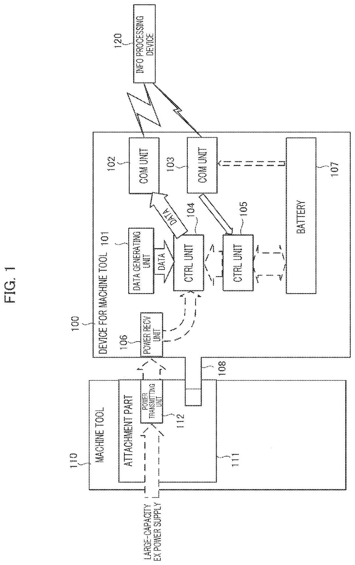
[0021]A device 100 for a machine tool according to a first embodiment will be described with reference to FIG. 1. The device 100 for a machine tool is a device that can be attached to and detached from a machine tool device attachment part 111 of a machine tool 110 (hereinafter simply referred to as an attachment part 111).

[0022]Examples of the device 100 for a machine tool include a camera, a measurement device, a laser scanner, an intelligent tool including a sensor for sensing vibration, temperature, or the like, and a light source of laser or the like.

[0023]Examples of the machine tool device attachment part 111 include a spindle of the machine tool, a pot of a magazine, a turret, a cover fixing part of a machine tool, and a fixing part on a side wall of a machine tool, serving as a tool attachment part.

[0024]As illustrated in FIG. 1, the device 100 for a machine tool includes a data generating unit 101, communication units 102 and 103, control units 104 and 105,...

Example

Second Embodiment

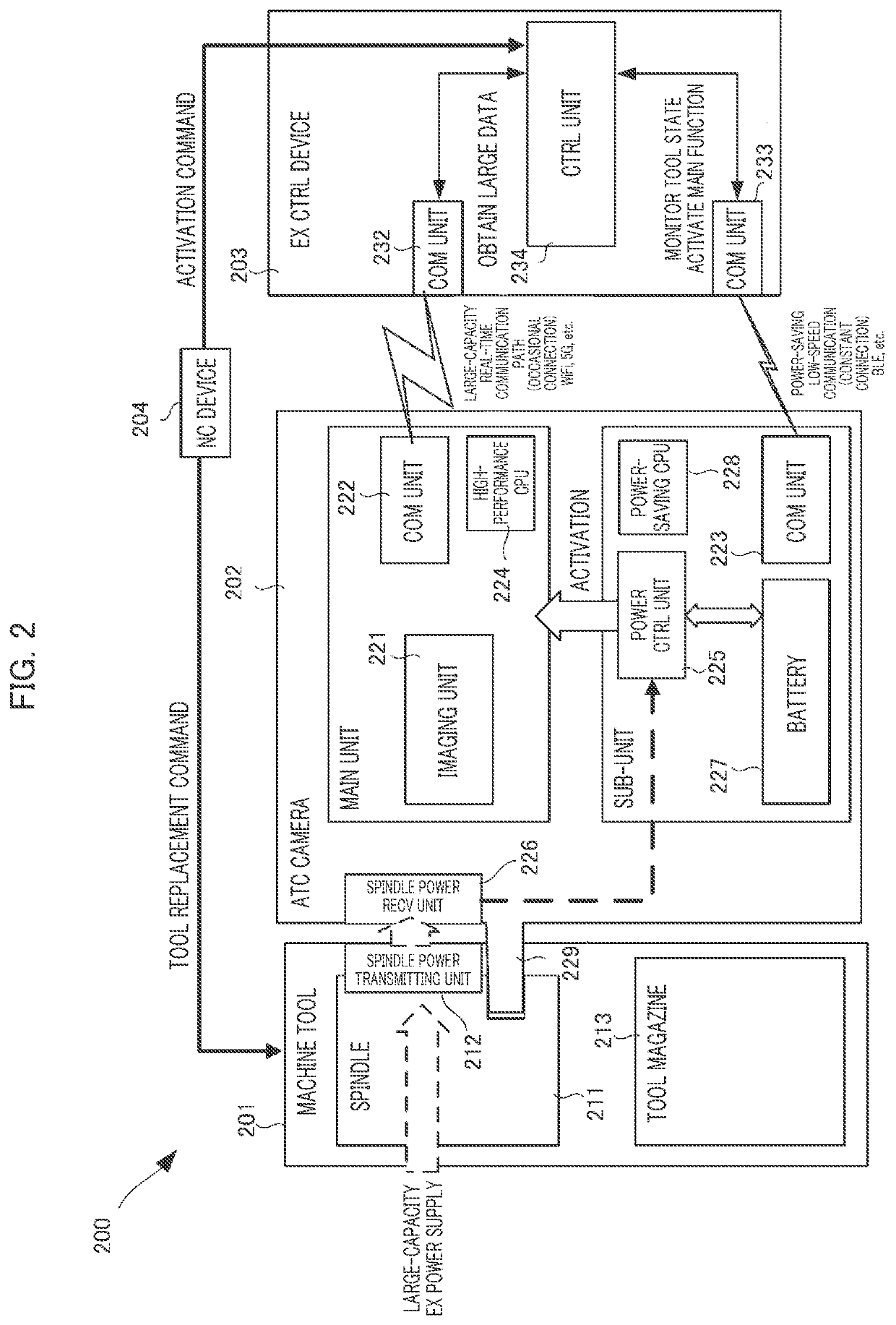
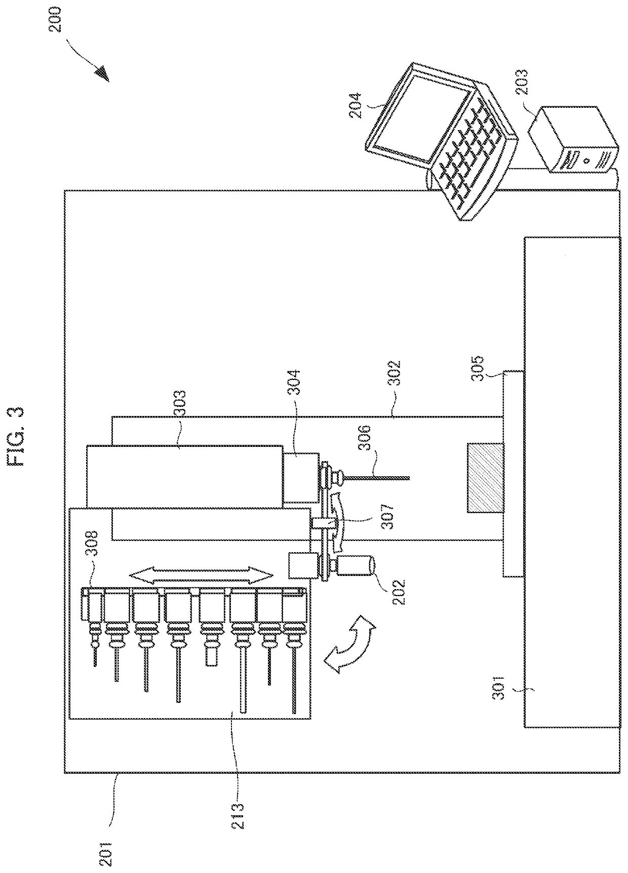
[0030]Next, a machine tool system 200 according to a second embodiment will be described with reference to FIG. 2 and subsequent drawings. FIG. 2 is a block diagram illustrating a functional configuration of the machine tool system 200.

[0031]As illustrated in FIG. 2, the machine tool system 200 includes a machine tool 201, an automatic tool changer (ATC) camera 202, which is an example of the device for a machine tool, an external control device 203, and a numerical control (NC) device 204.

[0032]The machine tool 201 includes actuators (such as a shaft driving actuator, a spindle driving actuator, a tool replacing actuator, a workpiece / pallet replacing actuator, a cooling mechanism actuator, and a chip conveying actuator), and sensors (such as a temperature sensor, a vibration sensor, a crash sensor, a light sensor, and a touch sensor), which are controlled by programs.

[0033]The NC device 204 includes a numerical controller (NC) and a programmable logic controller (P...


PUM


Abstract

A device for a machine tool, which is detachable from an attachment part of the machine tool, includes: a data generating unit that generates data; a first communication unit that transmits the data generated by the data generating unit to an information processing device; a first control unit that activates and controls the first communication unit; a power receiving unit that receives power supplied from outside and transmits the power to the first control unit; a second communication unit capable of constantly communicating with the information processing device; a battery that supplies power to the second communication unit; and a second control unit that supplies power from the battery to the first control unit to activate the first control unit when the second communication unit has received an activation command from the information processing device.

Description

CLAIM OF PRIORITY[0001]This application claims priority to Japanese Patent Application No. 2020-124720 filed on Jul. 21, 2020, which is incorporated herein by reference.BACKGROUND OF INVENTION1. Field[0002]The present invention relates to a device for a machine tool.2. Description of Related Art[0003]In this technical field, Patent Literature 1 teaches a sensor head 10 constituted by a body 12 and a collet chuck 18, in which a leading end of the body 12 includes a light emitting window 14 for irradiating a workpiece W with laser light L emitted by a non-contact sensor included in the sensor head 10, and a light receiving window 16 for receiving laser light (reflected light) R reflected by the surface of the workpiece W, and the collet chuck 18 having the same shape as each of collet chucks of tools accommodated in a tool magazine of a machining center is attached to a back end of the body 12. The sensor head 10 includes a secondary battery 106, and a wireless LAN unit 102, and trans...

Claims


Application Information

Patent Timeline
IPC IPC(8): G05B19/414H04N5/232H04N7/18H04N5/225H04W52/02
CPCG05B19/414H04N5/232411H04N7/183G05B2219/34315H04W52/0251G05B2219/34073H04N5/2257H04N7/185Y02D30/70H04N23/651H04N23/57
Inventor YAMAMOTO, KAZUYUKI
Owner DMG MORI SEIKI CO LTD
Why Eureka
Try Eureka