High flow therapy device utilizing a non-sealing respiratory interface and related methods

a technology of respiratory interface and high flow therapy, which is applied in the field of high flow therapy device utilizing a non-sealing respiratory interface, can solve the problems of provoking bronchospasm, limited treatment of certain types of nasal cannula, and detrimental to the health of users, so as to minimize the infection of the respiratory tract of the patien

Pending Publication Date: 2022-02-03
RESMED LTD
View PDF0 Cites 2 Cited by
  • Summary
  • Abstract
  • Description
  • Claims
  • Application Information

AI Technical Summary

Benefits of technology

[0012]The present disclosure also relates to a method of minimizing respiratory infections of a patient. The method includes providing a high flow therapy device, heating the gas and delivering the gas to a patient. The high flow therapy device of this method includes at least one heating element capable of heating a liquid to create a gas and a non-sealing respiratory interface configured to deliver the gas to a patient.

Problems solved by technology

However, treatment with certain types of nasal cannulas may be limited by the lack of information available on important treatment parameters.
In addition, prior art nasal cannula designs (especially those designed for neonatal oxygen therapy) may undesirably create a seal with the user's nares, which may have detrimental effects on the user's health.
This is true because breathing 100% O2 at room temperature via a nasal cannula is irritating to the nasal passage and is generally not tolerated above about 7-8 L / min.
Simply increasing the flow rate may also provoke bronchospasm.
This method is mostly employed in emergency situations and is generally not tolerated well for extended therapy.

Method used


Image

  • High flow therapy device utilizing a non-sealing respiratory interface and related methods
  • High flow therapy device utilizing a non-sealing respiratory interface and related methods
  • High flow therapy device utilizing a non-sealing respiratory interface and related methods

Examples


Embodiment Construction

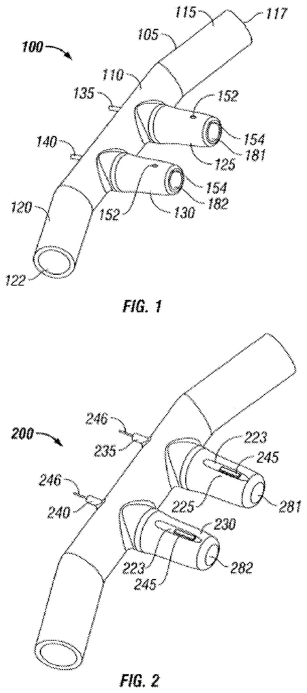
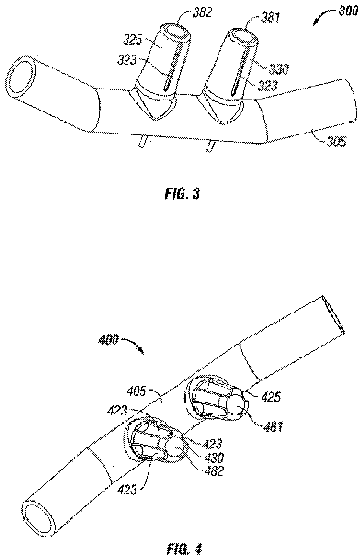
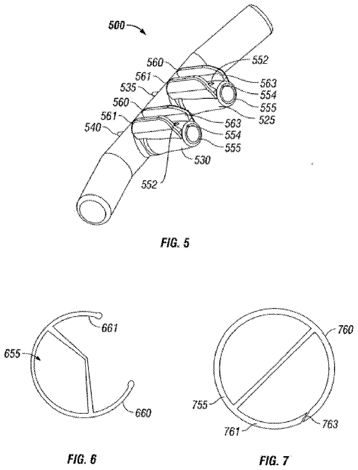
[0055]The present inventions now will be described with reference to the accompanying drawings, in which some, but not all embodiments of the inventions are shown. Indeed, these inventions may be embodied in many different forms and should not be construed as limited to the embodiments set forth herein. Rather, these embodiments are provided so that this disclosure will satisfy applicable legal requirements. Like numbers refer to like elements throughout. For example, elements 130, 230, 330, 430, 530, 830, and 930 are all nasal inserts according to various embodiments of the invention.

[0056]Overview of Functionality

[0057]Nasal cannula according to various embodiments of the invention may be configured to deliver high-flow therapeutic gases to a patient's upper airway through the patient's nose. Such gases may include, for example, air, humidity, oxygen, therapeutic gases or a mixture of these, and may be heated or unheated. In particular embodiments of the invention, the cannula may...


PUM


Abstract

A gas delivery conduit adapted for fluidly connecting to a respiratory gases delivery system in a high flow therapy system, the gas delivery conduit includes a first connector adapted for connecting to the respiratory gases delivery system, a second connector adapted for connecting to a fitting of a patient interface, tubing fluidly connecting the first connector to the second connector where the first connector has a gas inlet adapted to receive the supplied respiratory gas, one of electrical contacts and temperature contacts integrated into the first connector. The gas delivery conduit further can include a sensing conduit integrated into the gas delivery conduit, where the first connector of the gas delivery conduit is adapted to allow the user to couple the first connector with the respiratory gases delivery system in a single motion.

Description

CROSS-REFERENCE TO RELATED APPLICATIONS[0001]This application is a continuation of U.S. patent application Ser. No. 14 / 016,042, filed Aug. 30, 2013, which is a continuation of U.S. patent application Ser. No. 11 / 999,675, filed Dec. 6, 2007, now U.S. Pat. No. 8,522,782, and is a continuation-in-part of U.S. patent application Ser. No. 11 / 638,981, filed Dec. 14, 2006, now U.S. Pat. No. 8,333,194, which claims the benefit of U.S. Provisional Application Nos. 60 / 852,851, filed Oct. 18, 2006 and 60 / 750,063, filed Dec. 14, 2005. U.S. patent application Ser. No. 14 / 016,042 is also a continuation-in-part of U.S. patent application Ser. No. 11 / 520,490, filed Sep. 12, 2006, which claims the benefit of U.S. Provisional Patent Application Nos. 60 / 792,711, filed Apr. 18, 2006 and 60 / 716,776, filed Sep. 12, 2005, all of which are incorporated herein by reference.BACKGROUND OF THE INVENTION[0002]Respiratory interfaces, e.g., nasal cannulas are used to deliver respiratory gases for therapeutic effe...

Claims


Application Information

Patent Timeline
Patent Type & Authority Applications(United States)
IPC IPC(8): A61B5/0205A61M16/10A61M16/16A61M16/04A61M16/06A61M16/08A61J7/00A61M16/00A61B5/1455
CPCA61B5/0205A61J17/001A61M16/16A61M16/0488A61M16/049A61M16/0677A61M16/107A61M16/161A61M16/0858A61M16/085A61J7/0053A61M16/0069A61M16/0051A61M16/024A61M16/0666A61B5/14551A61M16/0816A61M2205/502A61M2202/0208A61M2016/1025A61M2016/0021A61M2016/103A61M2205/3368A61M2205/18A61M16/0066A61M2016/0039A61M16/1075A61J11/0005A61M16/0493A61M16/109A61M16/12A61M16/125A61M16/142A61M16/18A61M16/203A61M2016/0024A61M2205/3653A61M2205/50A61M2230/432A61M2230/435A61M2230/50A61M16/0875A61M2205/3334A61M2230/205A61M2230/42A61M2205/6045A61M2209/10A61M16/209A61M2205/21A61M2205/3306A61M2205/3386A61M2209/045A61M2205/581A61M2205/583A61M2209/082A61M2205/276A61M2205/3317A61M2205/6027A61B5/01A61B5/0816A61B5/082A61B5/087A61B5/097A61B5/6802A61B5/682A61B5/6819A61B5/1117A61M2230/005A61M2202/0007A61M16/101
Inventor LANDIS, ROBERT M.LEWIS, CHARLES A.COLLAZO, LOUIS JAVIER
Owner RESMED LTD
Why Eureka
Try Eureka