Device and method for sterilizing a catheter system
a catheter system and device technology, applied in the field of devices and methods for sterilizing catheter systems, can solve the problems of increased operating costs, unnecessary burden, and unit may be rendered inoperable, and achieve the effect of reducing the risk of infection and minimizing the potential for contamination
- Summary
- Abstract
- Description
- Claims
- Application Information
AI Technical Summary
Benefits of technology
Problems solved by technology
Method used
Image
Examples
first embodiment
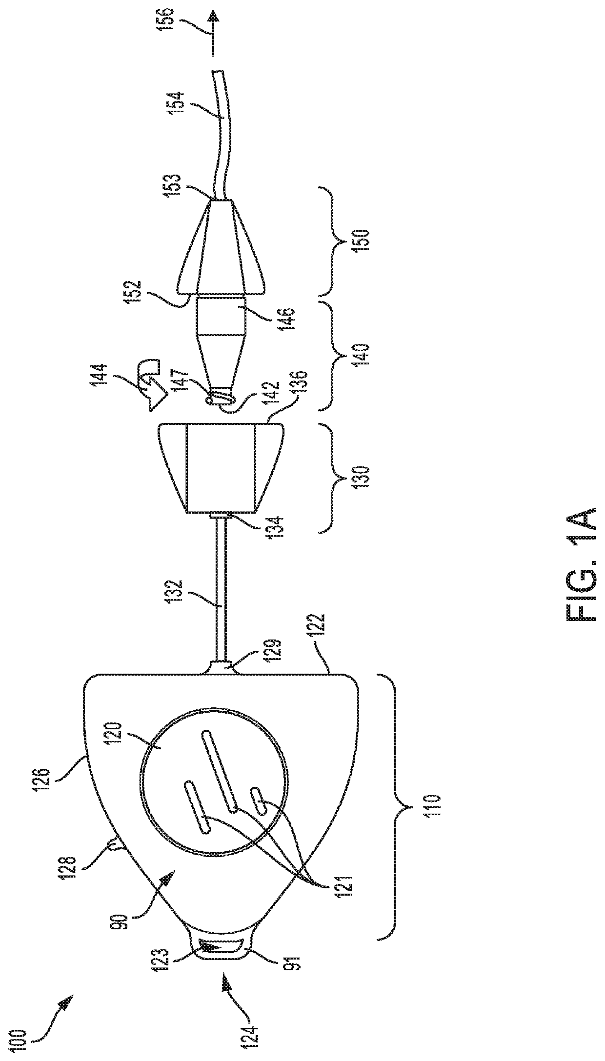
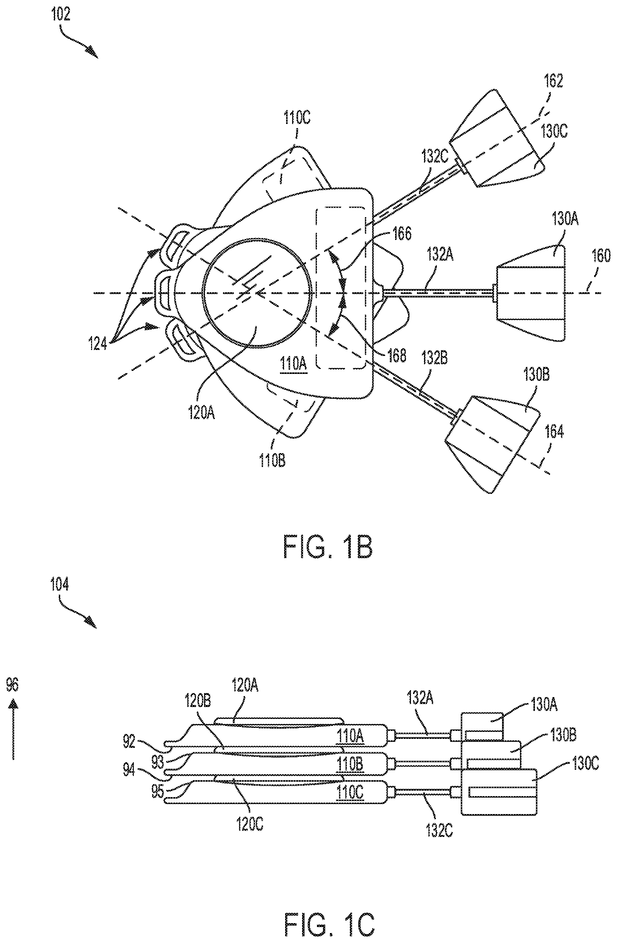
[0081]Referring to FIG. 1A, a schematic depiction is shown of a catheter device 100 for use in patient intravenous therapy. The catheter device 100 comprises catheter head unit 110 coupled via a connection line 132 to a luer port 130 with an ultra violet (UV) light source, and luer device 140 mounted axially to the luer port 130, and coupled to an extension component 150 with a catheter line 154. The catheter device 100 may be connected via the catheter line 154 to one or more access sites on a patient, as shown by the arrow 156.
[0082]As shown in FIG. 1A, the catheter head unit 110 includes a battery 120, mounted in a center region of the head unit 110. As an example, the battery 120 may comprise one or more rechargeable batteries mounted inside an interior region of the catheter head unit 110. The battery 120 may include one or more recesses and / or protrusions 121, for example. In one example, the recesses and / or protrusions 121 may connect to another catheter head unit, thereby co...
second embodiment
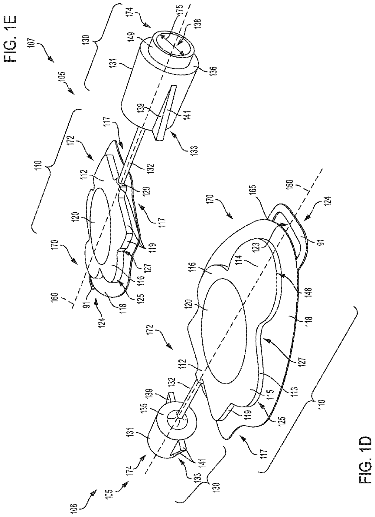
[0091]Referring to FIGS. 1D-E, a first view 106 and second view 107, respectively of a catheter device 105 is shown. The catheter device 105 includes a head unit 110 connected to a luer port 130 via a connection line 132. The head unit 110 includes a battery 120 centrally mounted in an interior region of the head unit. Although not shown, the head unit 110 may include an electronic control system for activating an ultra-violet (UV) light source mounted inside the luer port 130. The catheter device 105 may have an upstream end 170 and a downstream end 174.
[0092]The battery 120 may include one or more rechargeable batteries to power the catheter device 105. The battery 120 may be surrounded by elongated circular discs 115 and 116 disposed on either side of central axis 160. In addition, the battery 120 is surrounded by an oblate disc 114 having a curved section 148 formed at the upstream end 170 of the catheter device 105, and a geometric portion 112 formed at a middle portion 172. Th...
third embodiment
[0094]Referring to FIGS. 1F-G, a first view 108 and second view 109, respectively of a catheter device 111 is shown. The catheter device 111 includes a head unit 110 connected to a luer port 130 via a connection line 132. The head unit 110 includes a battery 120 centrally mounted in an interior region of the head unit. Although not shown, the head unit 110 may include an electronic control system for activating a ultra-violet light source mounted inside the luer port 130. The catheter device 111 may have an upstream end 170 and a downstream end 174.
[0095]As shown in FIGS. 1F-G, the battery 120 may be mounted on a circular disc 157 formed on a flat surface 118 of the catheter head unit 110. As an example, the battery 120 of catheter device 111 may comprise rechargeable batteries smaller in diameter compared to the battery of catheter device 105 disclosed with references to FIGS. 1D-E. In one example, the battery 120 may include one or more rechargeable batteries stacked together to p...
PUM
| Property | Measurement | Unit |
|---|---|---|
| wavelength | aaaaa | aaaaa |
| wavelengths | aaaaa | aaaaa |
| wave length | aaaaa | aaaaa |
Abstract
Description
Claims
Application Information
 - R&D
- Intellectual Property
- Life Sciences
- Materials
- Tech Scout
- Unparalleled Data Quality
- Higher Quality Content
- 60% Fewer Hallucinations
Browse by: Latest US Patents, China's latest patents, Technical Efficacy Thesaurus, Application Domain, Technology Topic, Popular Technical Reports.
© 2025 PatSnap. All rights reserved.Legal|Privacy policy|Modern Slavery Act Transparency Statement|Sitemap|About US| Contact US: help@patsnap.com


