

Self-adhering film with aerodynamic performance
- Summary
- Abstract
- Description
- Claims
- Application Information
AI Technical Summary
Benefits of technology
Problems solved by technology
Method used
Image

Examples
first embodiment
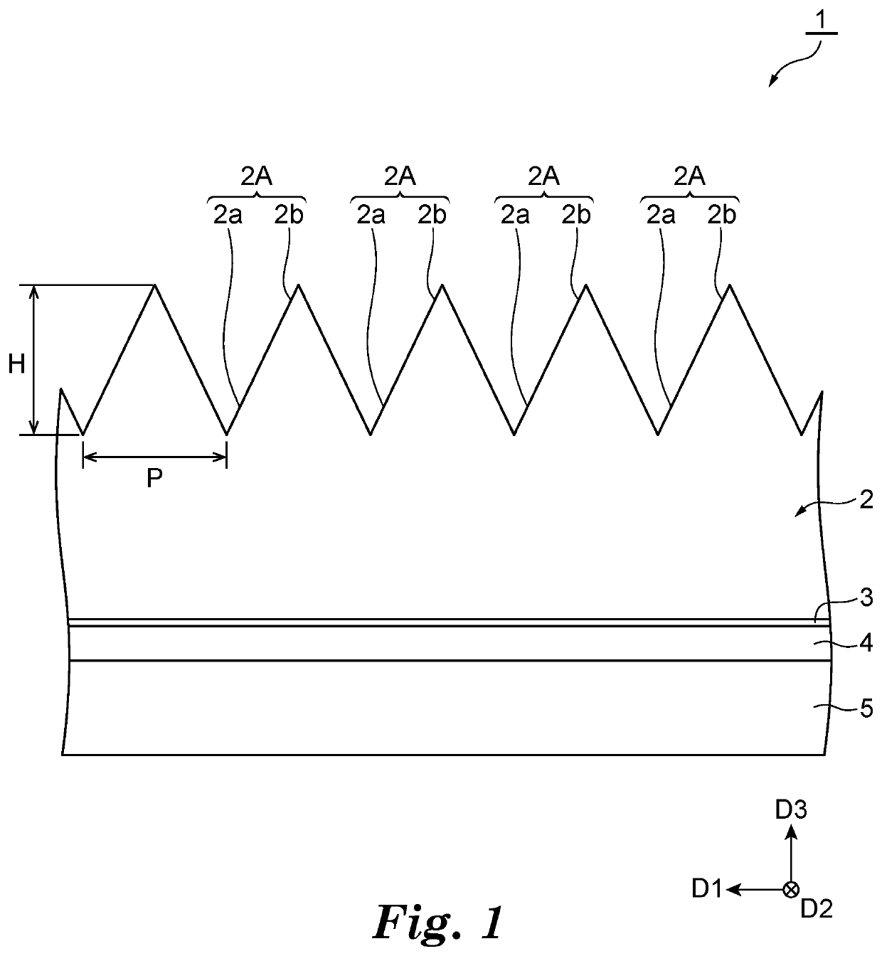
[0032]As illustrated in FIG. 1, a film 1 according to a first embodiment is, for example, attached to a surface of a moving body, and enhances aerodynamic performance of the moving body. The film 1 is attached to the surface of the moving body, and thus air resistance against the moving body is reduced. FIG. 1 is a view illustrating a laminating structure of the film 1. In the film 1, a base layer 2, a primer layer 3, an adhesive agent layer 4, and a release liner 5 are laminated in the stated order from the front side (a side opposite to the surface positioned on the moving body side at the time of being attached to the moving body).
[0033]For example, the material of the base layer 2 includes at least any of polyvinyl chloride (PVC), titanium dioxide, phosphate ester, diisobutyl ketone, solvent naphtha, diabenazole, an acrylic polymer, polyurethane, polyvinylidene fluoride (PVDF), a polymethyl methacrylate resin (PMMA), and an alloy of PVDF and PMMA. The base layer 2 may include at...
second embodiment
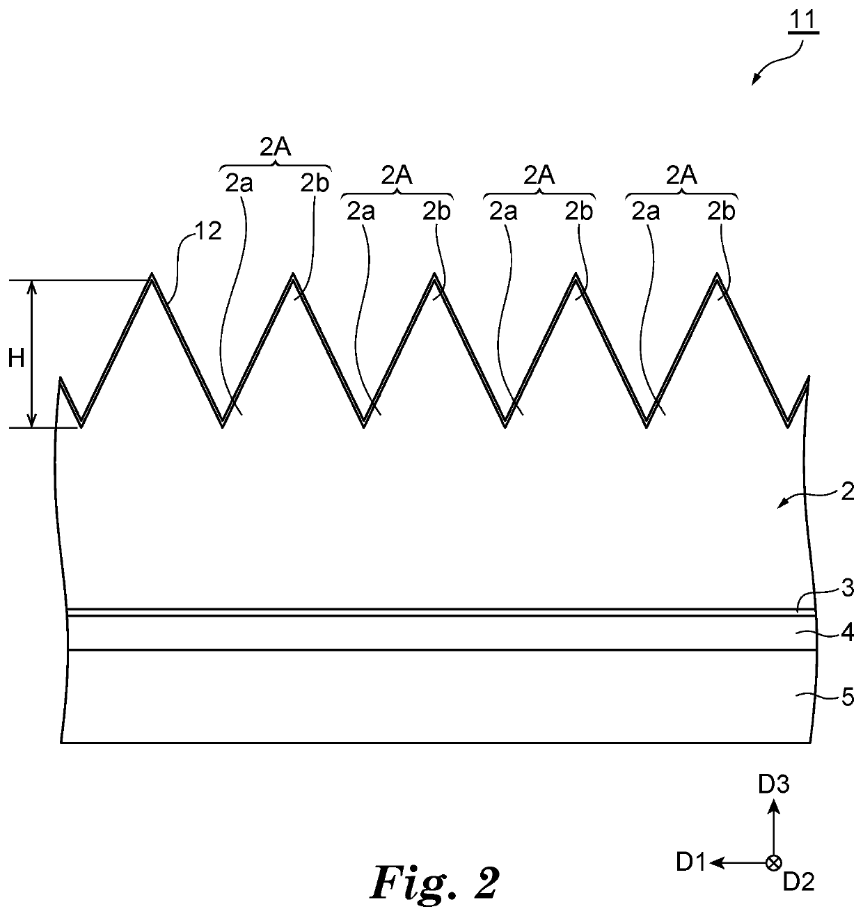
[0040]Next, a film 11 according to a second embodiment is described with reference to FIG. 2. As illustrated in FIG. 2, the film 11 is different from that in the first embodiment in that the recesses and protrusions 2A of the base layer 2 are further coated with a hydrophilic coating layer 12. In the following description, descriptions matching those in the embodiment described above are omitted as appropriate. Incidentally, “hydrophilicity” indicates a property that tends to bind to water or a property that tends to be dissolved in water, and the “hydrophilic coating layer” indicates a coating layer that enhances hydrophilicity.
[0041]The hydrophilic coating layer 12 has, for example, a self-cleansing function (a self-cleaning function). As described above, the recesses and protrusions 2A of the base layer 2 form a fine structure, which reduces air resistance and enhances aerodynamic performance. When the recesses and protrusions 2A are caused to exert a function of enhancing aerody...
third embodiment
[0049]Next, a film 21 according to a third embodiment is described. As illustrated in FIG. 6b, the film 21 is different from those in the embodiments described above in that a printed layer 23 is provided in place of the primer layer 3. For example, the printed layer 23 is an intermediate layer positioned between the recesses and protrusions 2A and the adhesive agent layer 4, and a layer subjected to printing. Further, in the film 21, the base layer 2 may be transparent. In this case, printing on the printed layer 23 can be clear. For example, on the printed layer 23, at least any of a character, a pattern, a drawing, and a picture may be printed. As one example, the printed layer 23 may display information relating to the moving body or may decorate the moving body. In this case, design of the moving body can be improved by the printed layer 23.
[0050]As a method of manufacturing the film 21, for example, first, a laminated body obtained by peeling the peeling member 15 off form the...
PUM
| Property | Measurement | Unit |
|---|---|---|
| Current | aaaaa | aaaaa |
| Hydrophilicity | aaaaa | aaaaa |
| Hydrophobicity | aaaaa | aaaaa |
Abstract
Description
Claims
Application Information