Method and system for arranging swarming drones
a drone and swarm technology, applied in the field of stackable drones, can solve the problems of waste of storage space and inconvenience in transportation, and achieve the effect of more eye-catching and entertaining
- Summary
- Abstract
- Description
- Claims
- Application Information
AI Technical Summary
Benefits of technology
Problems solved by technology
Method used
Image
Examples
embodiment 1
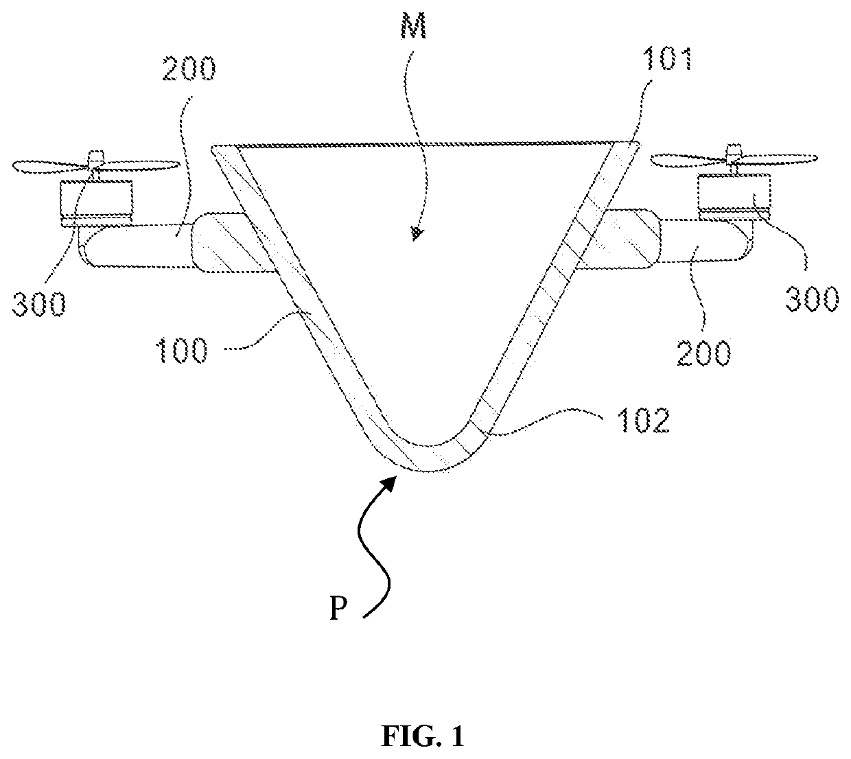
[0030]Referring to FIG. 1. A stackable drone is provided in the present embodiment. The stackable drone comprises a fuselage 100. The fuselage 100 is a main body of the drone. The fuselage 100 comprises a first end 101 and a second end 102. The fuselage is configured to taper gradually from the first end 101 to the second end 102 such that cross-sectional area of the first end 101 is greater than cross-sectional area of the second end 102. Preferably, the first end 101 is an upper end of the fuselage 100, the second end 102 is a lower end of the fuselage 100. In other words, cross section of the fuselage 100 decreases gradually from the upper end to the lower end, with the second end 102 protruding downward. Furthermore, the fuselage 100 may have a housing structure (or mating structure) arranged with an accommodating groove (or mating recess) M therein. The mating recess M has an opening at the first end 101. The mating recess M has a shape in conformity with exterior contour of th...
embodiment 2
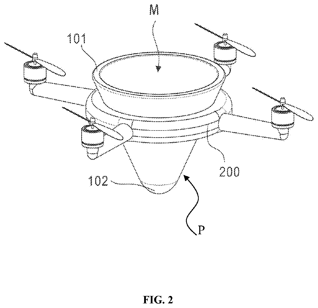
[0033]Referring to FIGS. 1-2. A second embodiment according to the present invention is provided. This embodiment is based on the first embodiment and different from the previous embodiment in that: preferably, longitudinal cross-section of the fuselage 100 is in V-shape. The longitudinal cross-section of corresponding mating recess M is in V-shape. As V-shaped structure is convenient to be stacked and taken out, convenience and effectiveness in storage and transportation can be achieved.
[0034]Furthermore, outer profile of any lateral cross section cut through from the first end 101 to the second end 102 of the fuselage 100 is circular, so that the fuselage 100 of the drone can be landed at any angle of orientation. Preferably, the outer contour of the fuselage 100 is shaped as a cone. The first end 101 is the base of the cone. The mating recess M is a cone-shaped groove. Conical shape is more convenient for landing and taking off than pyramid shape. The fuselage 100 further compris...
embodiment 3
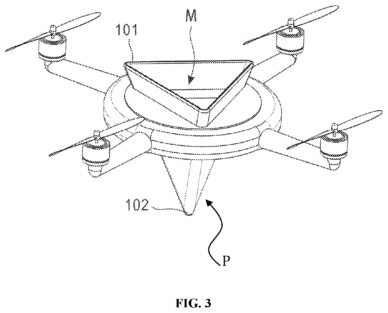
[0037]Referring to FIGS. 3-4. A third embodiment according to the present invention is provided. This embodiment is based on the previous embodiments and different from the previous embodiments in that: preferably, the fuselage 100 has a polygonal pyramid shape. Specifically, fuselage further comprises a circumferential side wall defining lateral cross-sections cut through any points from the first end to the second end of the fuselage to have n-sided polygonal ring shapes with respective n-sided polygonal outer profiles and consistent ring widths, where n is an integer and n≥3. The shape of the fuselage 100 may be triangular pyramid, quadrangular pyramid . . . etc. Preferably, depth of the mating recess M is greater than a vertical distance between the connection element 200 and the leading end 102 of the mating projection P. If the depth of the mating recess M is too short, the mating projection cannot be completely fit into the mating recess M, the landing of the drone will be un...
PUM
 Abstract
Description
Claims
Application Information
 - R&D
- Intellectual Property
- Life Sciences
- Materials
- Tech Scout
- Unparalleled Data Quality
- Higher Quality Content
- 60% Fewer Hallucinations
Browse by: Latest US Patents, China's latest patents, Technical Efficacy Thesaurus, Application Domain, Technology Topic, Popular Technical Reports.
© 2025 PatSnap. All rights reserved.Legal|Privacy policy|Modern Slavery Act Transparency Statement|Sitemap|About US| Contact US: help@patsnap.com


