Capacitor circuit and variable capacitance system including the same

Active Publication Date: 2022-02-10
SAMSUNG ELECTRO MECHANICS CO LTD
View PDF11 Cites 0 Cited by
  • Summary
  • Abstract
  • Description
  • Claims
  • Application Information

AI Technical Summary

Benefits of technology

The patent describes a capacitor circuit that includes two banks of capacitors that can be controlled by a controller to tune the impedance of an antenna. The first bank has p switch-capacitor circuits with different capacitance values based on a first weight, while the second bank has p+1 switch-capacitor circuits with different capacitance values based on a second weight. The circuits can be turned on or off by control bits, and the first and second weights can be different. The technical effect of this invention is to provide a more efficient and effective way to tune the impedance of an antenna.

Problems solved by technology

Accordingly, the design of a multi-band antenna has become increasingly difficult and complicated.
Such a binary weight value method may not be suitable for tuning the impedance of the multi-band antenna.
An array capacitor to which the binary weight value method is applied can provide capacitance values having a uniform distribution, but the impedance matching frequency of the multi-band antenna does not have a uniform distribution.
As a result of this, there is a limitation in effectively tuning various frequency bands when tuning multi-band antenna using the binary weight value method.

Method used


Image

  • Capacitor circuit and variable capacitance system including the same
  • Capacitor circuit and variable capacitance system including the same
  • Capacitor circuit and variable capacitance system including the same

Examples


Embodiment Construction

[0040]The following detailed description is provided to assist the reader in gaining a comprehensive understanding of the methods, apparatuses, and / or systems described herein. However, various changes, modifications, and equivalents of the methods, apparatuses, and / or systems described herein will be apparent after an understanding of the disclosure of this application. For example, the sequences of operations described herein are merely examples, and are not limited to those set forth herein, but may be changed as will be apparent after an understanding of the disclosure of this application, with the exception of operations necessarily occurring in a certain order. Also, descriptions of functions and constructions that are known in the art may be omitted for increased clarity and conciseness.

[0041]The features described herein may be embodied in different forms, and are not to be construed as being limited to the examples described herein. Rather, the examples described herein hav...


PUM


Abstract

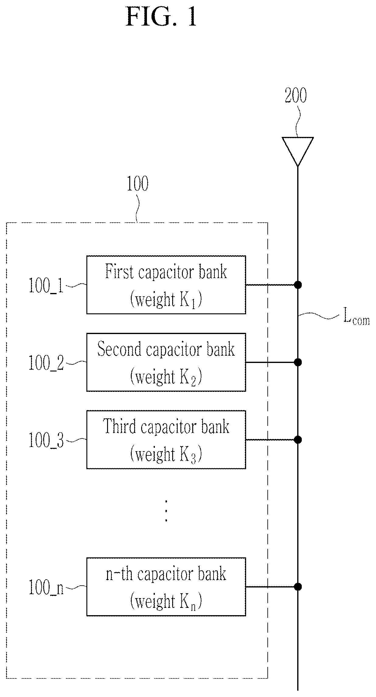
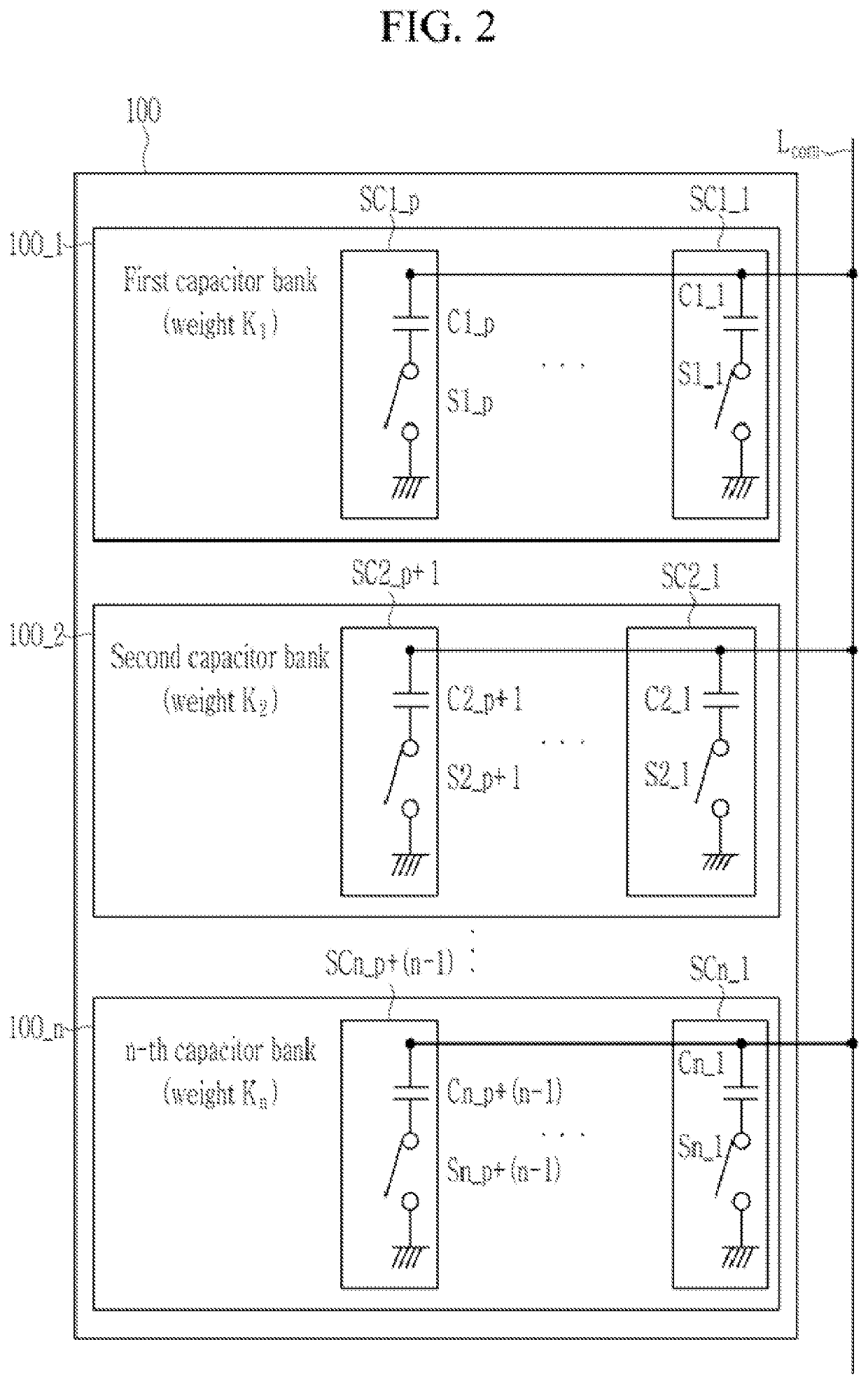
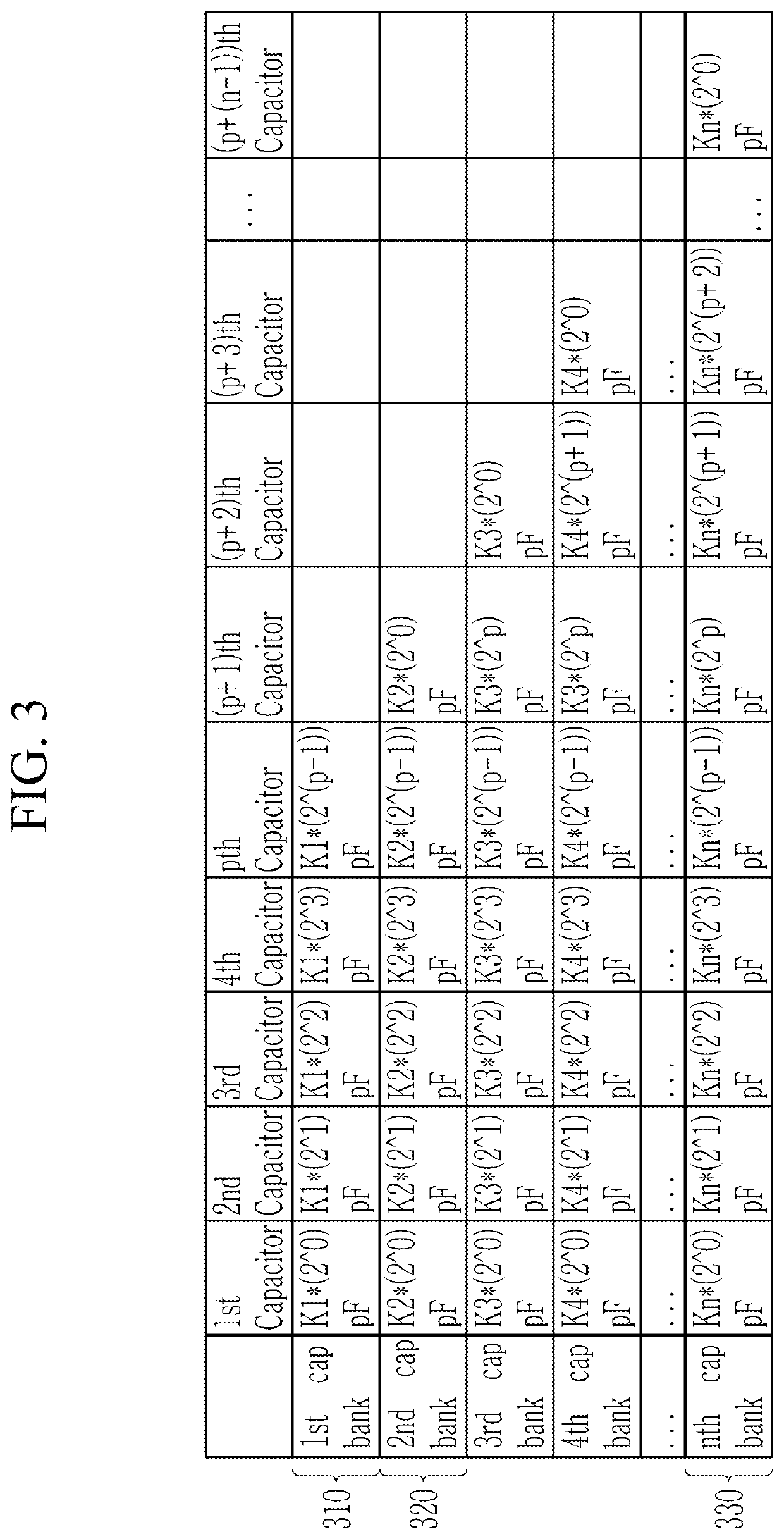
A capacitor circuit includes a first capacitor bank and a second capacitor bank. The first capacitor bank includes p switch-capacitor circuits connected to each other in parallel, where p is a natural number of 2 or more, wherein at least two switch-capacitor circuits among the p switch-capacitor circuits have mutually different capacitance values based on a first weight. The second capacitor bank includes q switch-capacitor circuits connected to each other in parallel, where q is a natural number greater than p, wherein at least two of the q switch-capacitor circuits have mutually different capacitance values based on a second weight different from the first weight.

Description

CROSS-REFERENCE TO RELATED APPLICATIONS[0001]This application claims the benefit under 35 USC 119(a) of Korean Patent Application No. 10-2020-0097594 filed on Aug. 4, 2020, in the Korean Intellectual Property Office, the entire disclosures of which is incorporated herein by reference for all purposes.BACKGROUND1. Field[0002]This application relates to a capacitor circuit and a variable capacitance system including the same.2. Description of Related Art[0003]Various frequency bands have been used in recent communication systems, and a radio-frequency (RF) device in these communication systems needs to support the various frequency bands. Accordingly, the design of a multi-band antenna has become increasingly difficult and complicated. To support a multi-band antenna, there is a need for a switch that is capable of adjusting the impedance of the multi-band antenna.[0004]As a method for adjusting the impedance of an antenna, an array capacitor has been proposed. To provide various capa...

Claims


Application Information

Patent Timeline
IPC IPC(8): H01Q5/50H01Q5/328
CPCH01Q5/50H01Q5/328H04B1/006H04B1/40H01Q5/335H04B1/0458H03H7/40H04B1/18H03H2210/025H03M1/802H01G17/00H01G7/00
Inventor PAEK, HYUNHWANG, WONSUNHUR, YOUNGSIKNA, YOOSAM
Owner SAMSUNG ELECTRO MECHANICS CO LTD
Why Eureka
Try Eureka