Display Device and Luminance Control Method Thereof and Mobile Terminal Using the Same

a technology of luminance control and display device, which is applied in the direction of computing, instruments, climate sustainability, etc., can solve the problems of reducing reducing the brightness limiting the screen size, so as to achieve uniform luminance of the entire screen, reduce the lifetime of pixels, and reduce the effect of high voltag

Active Publication Date: 2022-02-17
LG DISPLAY CO LTD
View PDF5 Cites 3 Cited by
  • Summary
  • Abstract
  • Description
  • Claims
  • Application Information

AI Technical Summary

Benefits of technology

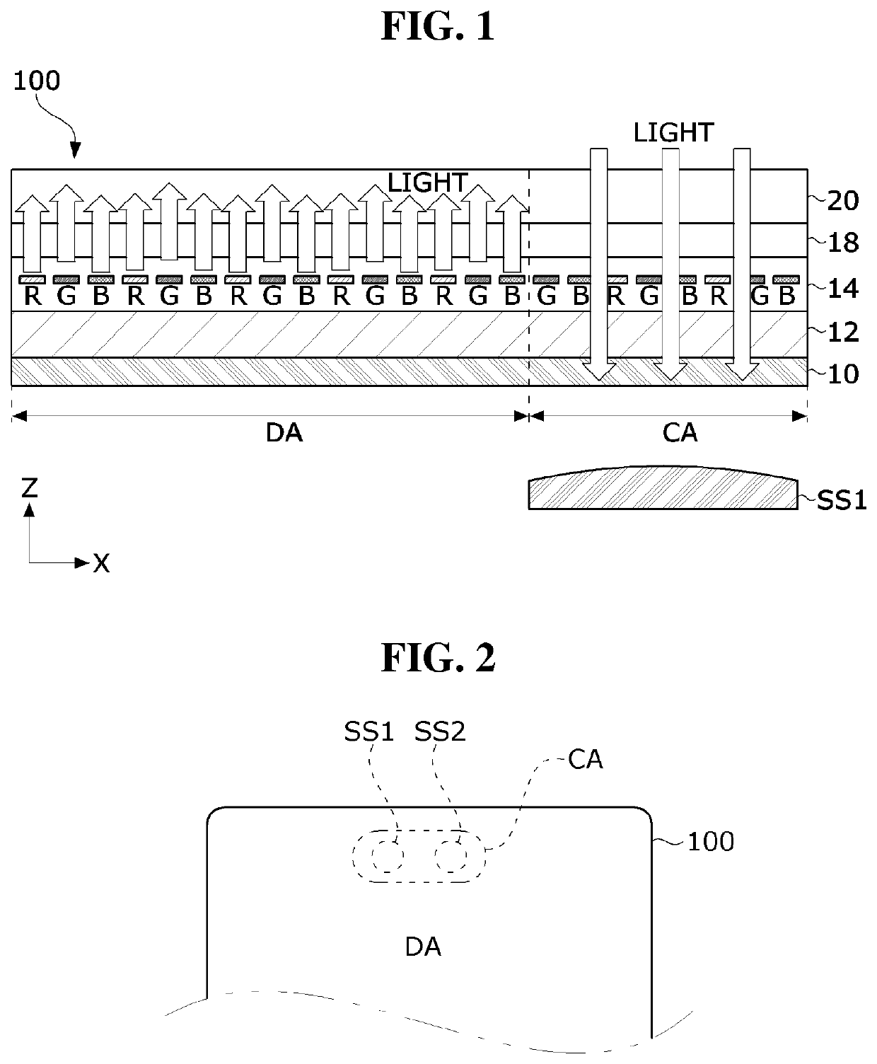
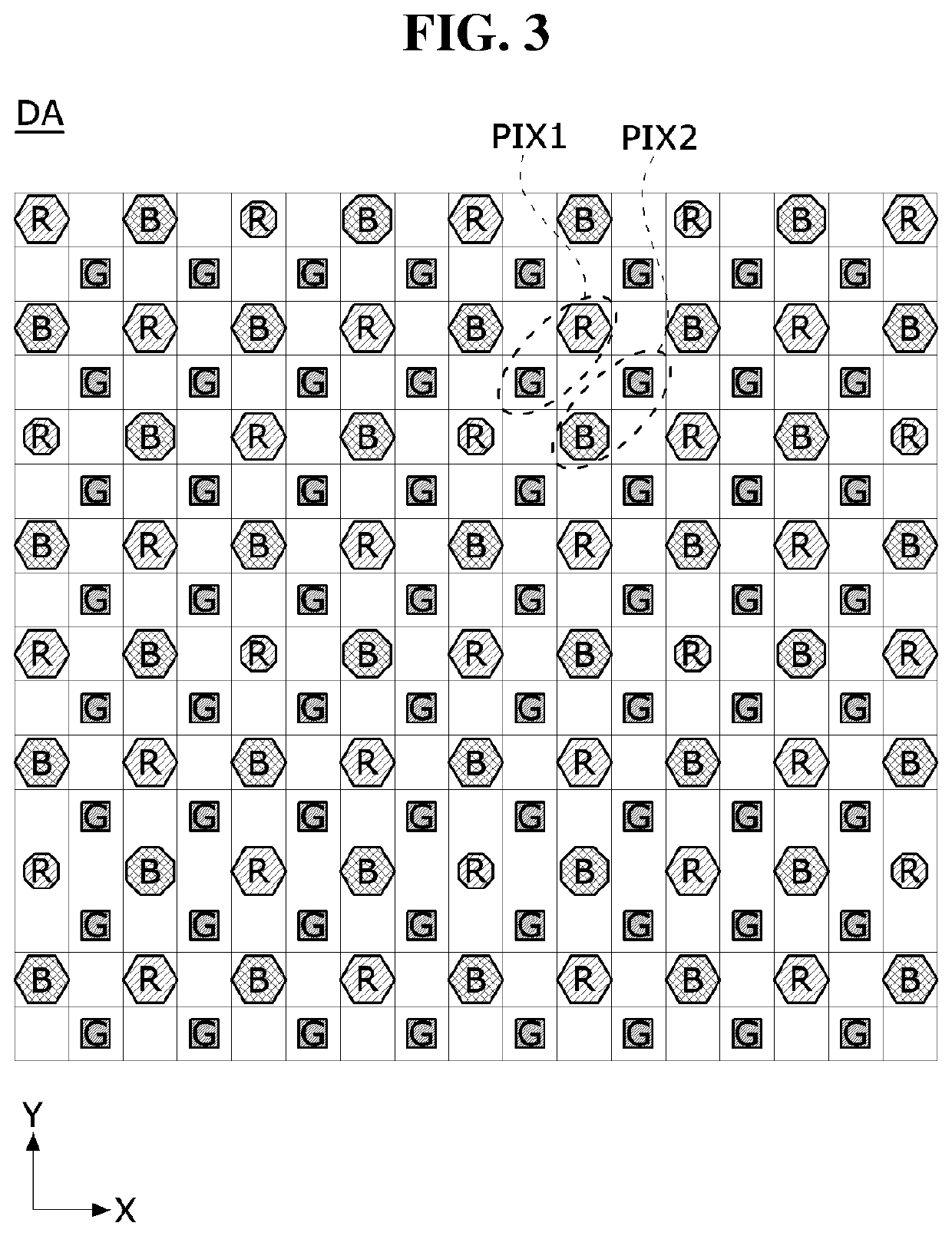
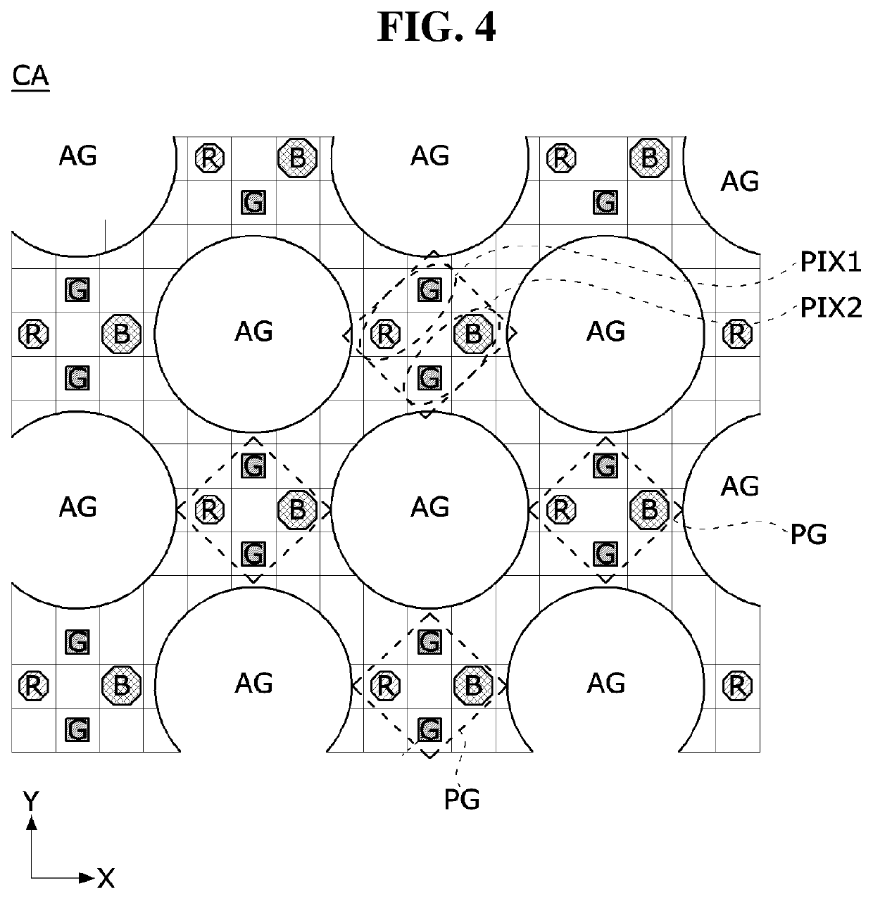
[0005]In order to implement a full-screen display, a sensing region in which low-resolution pixels may be disposed within a screen of a display panel may be provided. Since the number of pixels lighted in such a sensing region is relatively small, the uniformity of luminance of the entire screen may be driven by a relatively high voltage to the pixels in the sensing region. In this case, the deterioration of the pixels in the sensing region is accelerated compared to the pixels in the high-resolution region, so that the lifetime of the pixels may be shortened. In addition, power consumption may be different for each region of the screen, and a difference in power consumption may occur for each channel of the data driver.

Problems solved by technology

However, the front camera of a smart phone restricts the screen design, making it difficult to design the screen.
In order to reduce the space occupied by the camera, a screen design including a notch or a punch hole has been adopted in smartphones, but the screen size is still limited due to the camera, and a full-screen display could have not been implemented.
In addition, power consumption may be different for each region of the screen, and a difference in power consumption may occur for each channel of the data driver.

Method used


Image

  • Display Device and Luminance Control Method Thereof and Mobile Terminal Using the Same
  • Display Device and Luminance Control Method Thereof and Mobile Terminal Using the Same
  • Display Device and Luminance Control Method Thereof and Mobile Terminal Using the Same

Examples


first embodiment

[0174]FIG. 18 is a flowchart illustrating a method of controlling luminance of a display device according to the present disclosure. The various embodiments of the following luminance control method may be implemented by the above-described display device, mobile terminal, and luminance control device.

[0175]Referring to FIG. 18, the luminance control method may analyze an input image and determine whether a touch input of the second pixel region CA is frequently generated or an image is a predicted application image (S181 and S182). In this step, the AI processor may predict whether or not an image in which a touch input may be frequently generated in the second pixel region CA. For example, in the case of a game, YouTube, or real-time video streaming, the user may view the screen of the mobile terminal 2000 horizontally and hold both sides of the mobile terminal with both hands as shown in FIG. 20. In this case, the second pixel region CA may be frequently touched by the finger or ...

second embodiment

[0178]FIG. 19 is a flowchart illustrating a method of controlling luminance of a display device according to the present disclosure.

[0179]Referring to FIG. 19, in the luminance control method, a touch input of the second pixel region CA is detected and the frequency is compared with a preset threshold Nth (S191 and S192).

[0180]The luminance control method controls the luminance of the second pixel region CA equal to the luminance of the first pixel region DA when the frequency of the touch input detected on the second pixel region CA within the reference time is less than the threshold value (S192 and S193). In this case, the luminance control method may control luminance of the first and second pixel regions DA and CA based on the gamma curve shown in FIG. 14.

[0181]In the luminance control method, as shown in FIG. 20, when the frequency of the touch input on the second pixel region CA within a reference time is greater than or equal to the threshold value Nth, the luminance of the ...

third embodiment

[0182]FIG. 21 is a flowchart illustrating a method of controlling luminance of a display device according to the present disclosure.

[0183]Referring to FIG. 21, the luminance control method senses movement and inclination of the mobile terminal 2000 in real time to determine whether the mobile terminal 2000 is horizontally or vertically reversed (rotated by)180° (S211 and S212).

[0184]In the luminance control method, when the mobile terminal 2000 is not rotated and the second pixel region CA is positioned at the top of the screen, the luminance of the second pixel region CA is controlled in the same manner as the luminance of the first pixel region DA(S211 and S213). If it is positioned at the top of the screen of the second pixel region CA, the user may easily recognize the change in luminance of the second pixel region CA. Accordingly, when the mobile terminal 2000 does not rotate and the second pixel region CA is positioned at the top of the screen, the luminance of the second pixe...


PUM


Abstract

The present disclosure relates to a display device, a luminance control method thereof, and a mobile terminal using the same. The display device includes a display panel in which a pixel array including at least a first pixel region and a second pixel region are disposed; a touch sensor disposed on the pixel array; a display panel driver configured to write pixel data of an input image to pixels in the first pixel region and the second pixel region; a touch sensor driver configured to drive the touch sensor and detect a touch input on the pixel array to generate touch coordinate data; and a luminance control device configured to lower the luminance of one of the first and second pixel regions in at least some gray scales when the touch input is detected on the pixel array.

Description

CROSS-REFERENCE TO RELATED APPLICATION[0001]This application claims priority to and the benefit of Republic of Korea Patent Application No. 10-2020-0102139, filed Aug. 14, 2020, the disclosure of which is hereby incorporated by reference in its entirety.BACKGROUND1. Field[0002]The present disclosure relates to a display device capable of controlling luminance of a screen for each region, a luminance control method thereof, and a mobile terminal using the same.2. Discussion of Related Art[0003]An electroluminescent display device is roughly classified into an inorganic light emitting display device and an organic light emitting display device depending on the material of a light emitting layer. The organic light emitting display device of an active matrix type includes an organic light emitting diode (hereinafter referred to as “OLED”) that emits light by itself (e.g., self-luminescent), and has an advantage that the response speed is fast, and the luminous efficiency, luminous and v...

Claims


Application Information

Patent Timeline
Patent Type & Authority Applications(United States)
IPC IPC(8): G09G3/3225G06F3/041G09G3/20G09G3/3275
CPCG09G3/3225G06F3/0416G09G3/2007G09G3/3275G09G2310/027G09G2320/043G09G2330/021G09G2354/00G09G2320/0686G09G2340/0407G09G2320/0673G09G3/3233G09G2360/16G06F1/1626G06F1/1643G06F1/1694G06F1/3215G06F1/3218G06F1/3265G06F1/3296Y02D10/00G09G3/2092G06F3/04817G09G2320/0233
Inventor HWANG, JONG HEEKWON, SU JIN
Owner LG DISPLAY CO LTD
Why Eureka
Try Eureka