

UV mapping on 3D objects with the use of artificial intelligence
a technology of artificial intelligence and 3d objects, applied in the field of computer graphics, can solve the problems of inefficiency of layout, inability to locate seams that are not located at semantic boundaries, and inability to optimize the space on the 2d image, so as to reduce the number of pieces required and minimize distortion
- Summary
- Abstract
- Description
- Claims
- Application Information
AI Technical Summary
Benefits of technology
Problems solved by technology
Method used
Image

Examples
Embodiment Construction
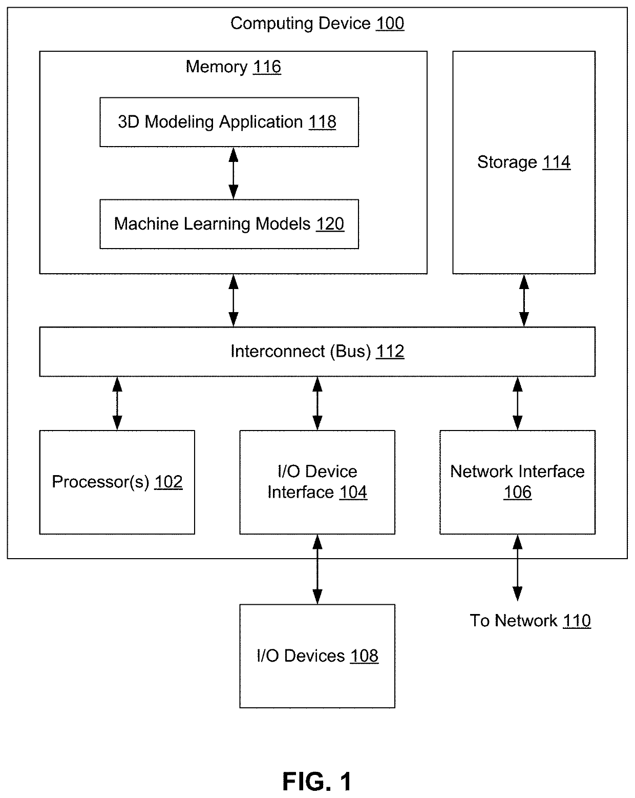
[0001]Embodiments of the present invention relate generally to computer graphics and, more specifically, to UV mapping on 3D objects with the use of artificial intelligence.
Description of the Related Art
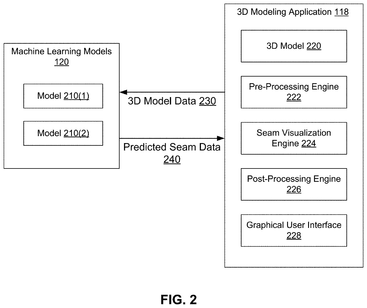
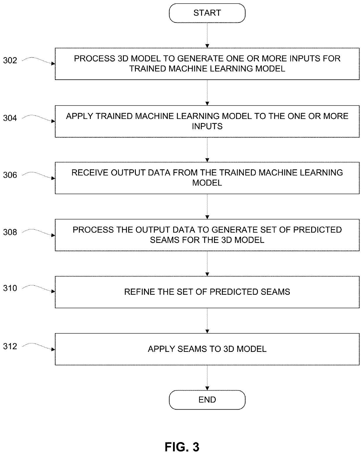
[0002]Three-dimensional (3D) graphics applications enable users to design and generate 3D models for various applications, including video games, special effects, design visualization, and printing physical articles based on the 3D model. 3D models are often textured using one or more 2D images via a UV mapping process. The UV mapping process typically involves defining a set of seams where the 3D model should be split, or divided, into one or more parts. The one or more parts are unwrapped or flattened into a single 2D image (two-dimensional UV space) so that a texture can be drawn on the 2D image. In such a manner, the texture on the 2D image is applied or “mapped” to the 3D model.
[0003]In UV mapping, the improper placement of seams on the 3D model can cause several problems. In pa...
PUM
 Abstract
Description
Claims
Application Information