Coil component

Pending Publication Date: 2022-02-24
TDK CORPARATION
View PDF0 Cites 0 Cited by
  • Summary
  • Abstract
  • Description
  • Claims
  • Application Information

AI Technical Summary

Benefits of technology

The present invention aims to reduce eddy currents in a coil component that is parallel to a substrate. This is done to prevent damage caused by eddy currents in the terminal electrode and its land pattern on the substrate.

Problems solved by technology

However, in the coil component described in JP 2007-095949A and JP 2013-187319A, the use of the air-core coil complicates the manufacturing process.
Further, the coil axis is perpendicular to the base member, so that a large amount of magnetic flux is applied to a terminal electrode and its corresponding land pattern formed on a substrate, which may easily cause an eddy current.
However, in the coil component described in JP 2018-010990A, the terminal electrode is directly formed on the magnetic core, so that the amount of magnetic flux to be applied to the terminal electrode and its corresponding land pattern cannot be reduced to a sufficient level.

Method used


Image

  • Coil component
  • Coil component
  • Coil component

Examples


first embodiment

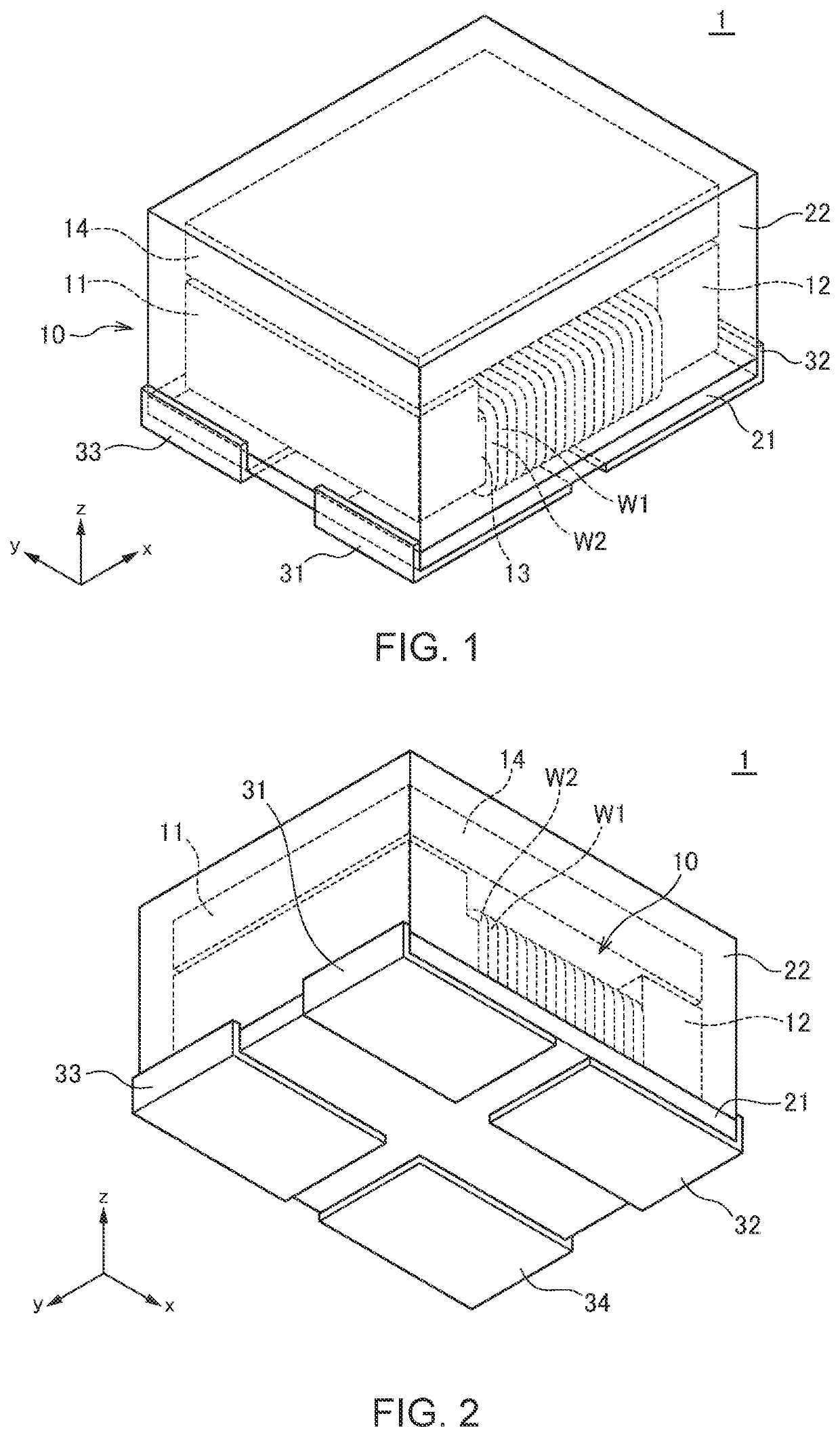
[0025]FIG. 1 is a schematic transparent perspective view illustrating the outer appearance of a coil component 1 according to the present invention. FIG. 2 is a schematic transparent perspective view of the coil component 1 as viewed in a different angle from the angle of FIG. 1.

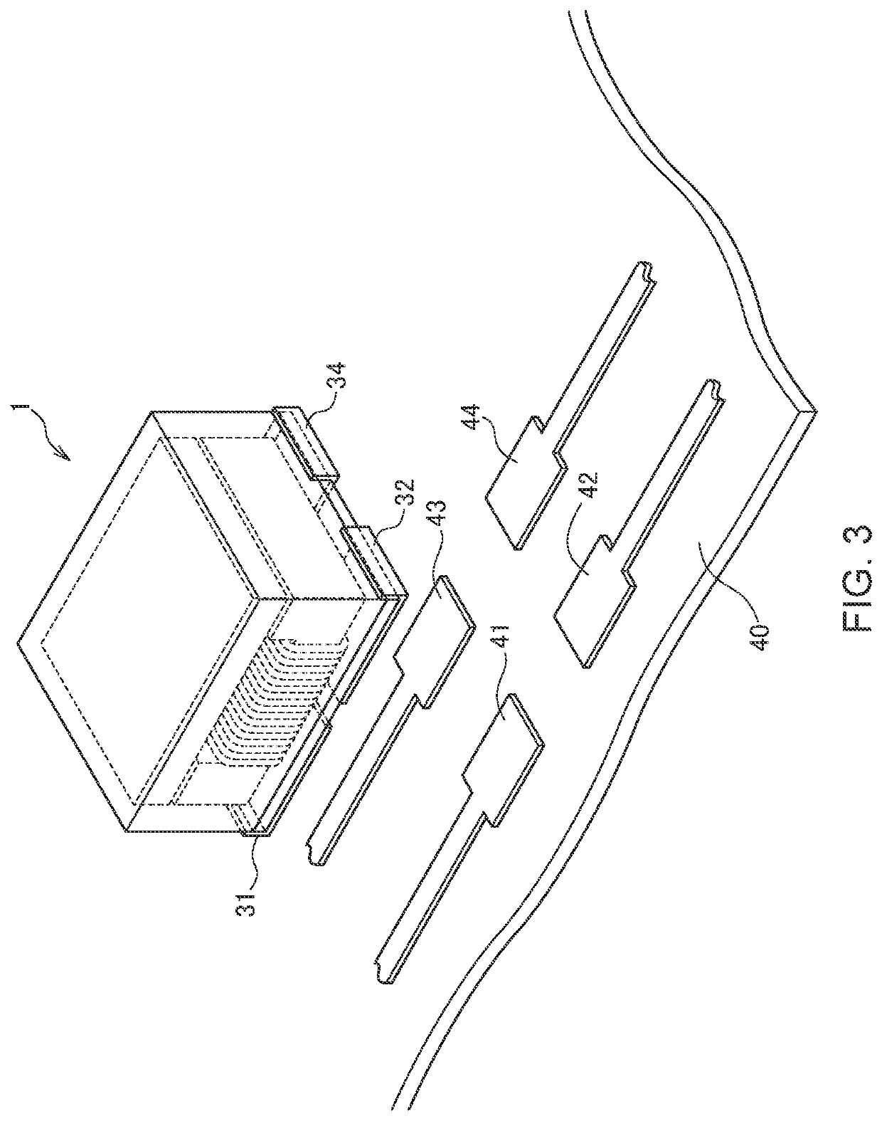
[0026]The coil component 1 according to the first embodiment is a common mode filter and includes, as illustrated in FIGS. 1 and 2, a flat plate-like base member 21, a magnetic core 10 mounted on the xy top surface of the base member 21, a plate-like core 14 fixed to the magnetic core 10, wires W1 and W2 wound around a winding core part 13 of the magnetic core 10, terminal electrodes 31 to 34 fixed to the base member 21, and a molding member 22 formed on the base member 21 so as to cover the magnetic core 10 and plate-like core 14. Both ends of wire W1 are connected respectively to the terminal electrodes 31 and 32, and both ends of the wire W2 are connected respectively to the terminal electrodes 33 and 34....

second embodiment

[0036]FIG. 6 is a schematic transparent perspective view illustrating the outer appearance of a coil component 2 according to the present invention.

[0037]The coil component 2 illustrated in FIG. 6 includes first and second coil parts 1A and 1B each having basically the same structure as the coil component 1 according to the first embodiment and sharing the base member 21 and molding member 22. With this configuration, the coil component 2 can be used as an array product in which two common mode filters are integrated into one chip. This allows a configuration in which terminal electrodes 31A to 34A provided in the coil component 1A and terminal electrodes 31B to 34B provided in the coil component 1B are connected to a first differential signal line and a second differential signal line, respectively.

third embodiment

[0038]FIG. 7 is a schematic transparent perspective view illustrating the outer appearance of a coil component 3 according to the present invention. FIG. 8 is a view illustrating a state where the magnetic core 10, plate-like core 14, and wires W1 and W2 are removed from the coil component 3. FIG. 9 is a view illustrating the structure of the base member 21.

[0039]As illustrated in FIGS. 7 to 9, the coil component 3 according to the third embodiment includes electronic components 61 and 62, such as a varistor, mounted on the surface of the base member 21. The electronic component 61 is inserted between connection patterns 72 and 75 formed on the surface of the base member 21, and the electronic component 62 is inserted between connection patterns 74 and 75 formed on the surface of the base member 21. The connection patterns 72, 74, and 75 are provided so as to overlap respectively through holes 52, 54, and 55 penetrating the base member 21. Thus, as illustrated in an equivalent circu...


PUM


Abstract

Disclosed herein is a coil component that includes a plate-like base member, a magnetic core mounted on the base member, a wire wound around the magnetic core such that an axis direction thereof is substantially parallel to the base member, and a terminal electrode fixed to the base member and connected to an end portion of the wire. The base member is made of a material having a permeability lower than that of the magnetic core.

Description

BACKGROUND OF THE INVENTIONField of the Invention[0001]The present invention relates to a coil component and, more particularly, to a coil component having a structure in which a wire is wound around a magnetic core made of ferrite or the like.Description of Related Art[0002]JP 2007-095949A and JP 2013-187319A disclose a coil component having a structure in which a coil body combining an air-core coil and a magnetic core is mounted on a base member. However, in the coil component described in JP 2007-095949A and JP 2013-187319A, the use of the air-core coil complicates the manufacturing process. Further, the coil axis is perpendicular to the base member, so that a large amount of magnetic flux is applied to a terminal electrode and its corresponding land pattern formed on a substrate, which may easily cause an eddy current.[0003]To solve such a problem, the coil axis is set parallel to the substrate by using a drum-shaped magnetic core as described in JP 2018-010990A. In the coil co...

Claims


Application Information

Patent Timeline
IPC IPC(8): H01F27/29H01F17/04H01F27/28
CPCH01F27/292H01F2017/048H01F27/2823H01F17/045H01F41/069H01F27/263H01F27/022
Inventor TOYODA, TERUMASASUZUKI, HIROSHITONOGAI, TORUHIGASHIDA, KEIGOYOSHINO, HANAKO
Owner TDK CORPARATION
Why Eureka
Try Eureka