
Optical system, projector, and imaging apparatus

a technology of optical system and imaging apparatus, which is applied in the direction of projectors, camera body details, instruments, etc., can solve the problems of heavy weight high manufacturing cost of glass optical elements, and insufficient magnification of optical systems, so as to achieve the suppression of manufacturing costs, the effect of easy increase of magnification provided by the optical system

Active Publication Date: 2022-03-03
SEIKO EPSON CORP
View PDF0 Cites 1 Cited by
  • Summary
  • Abstract
  • Description
  • Claims
  • Application Information

AI Technical Summary

Benefits of technology

The present patent text describes an optical system made of resin with a concave reflection surface that meets a certain condition. The system has a light modulator for projecting modulated light. It also includes an image display device for forming images using the system's optical system. The technical effect of this invention is to provide an optical system with improved image quality and reduced aberrations, allowing for better light modulation and image formation.

Problems solved by technology

An optical element made of glass is, however, heavy as compared with an optical element made of resin.
Furthermore, when optical elements having the same shape are manufactured, the manufacturing cost of optical elements made of glass is higher than that of optical elements made of resin in many cases.

Method used


Image

  • Optical system, projector, and imaging apparatus
  • Optical system, projector, and imaging apparatus
  • Optical system, projector, and imaging apparatus

Examples


example 1

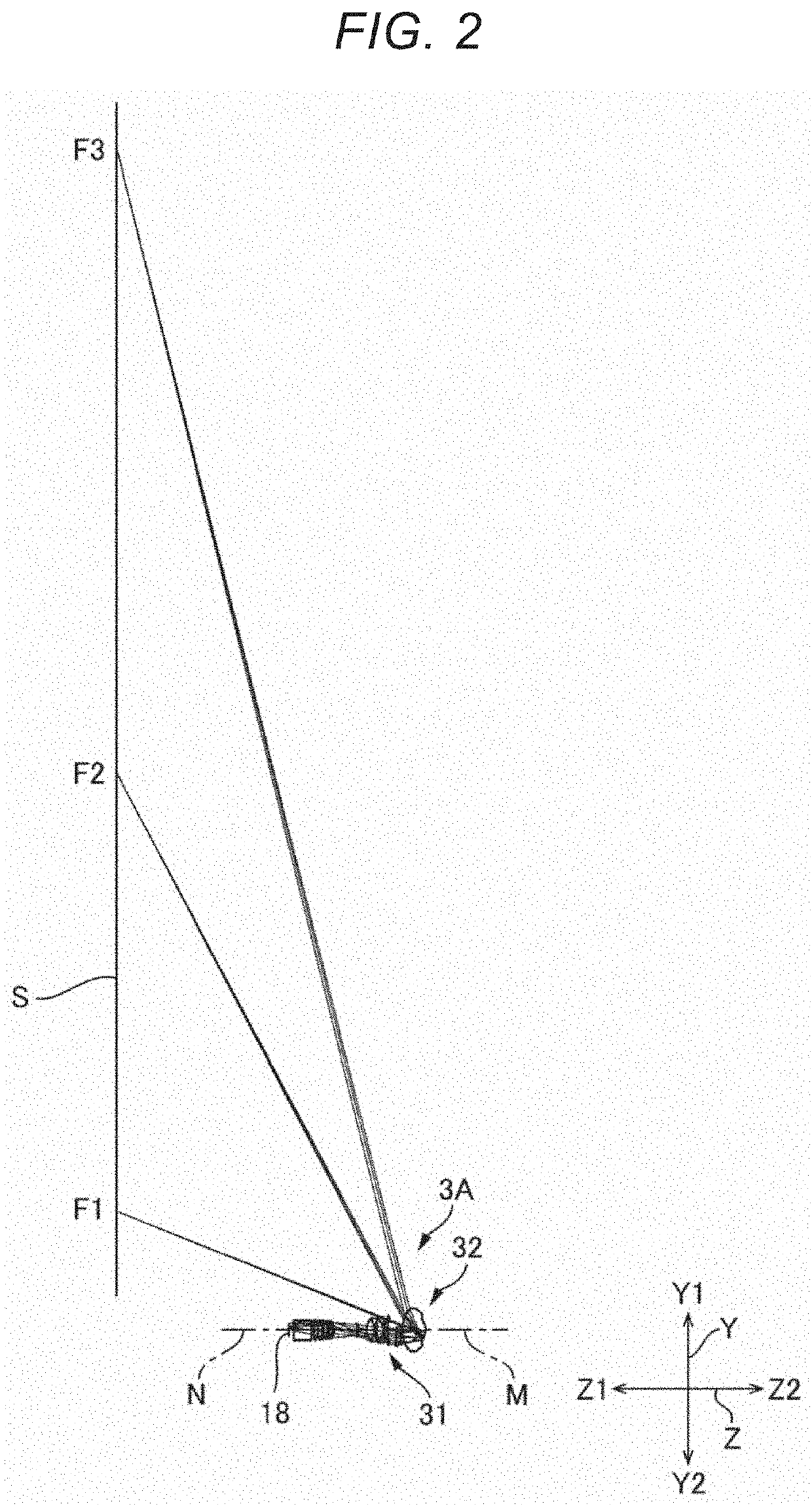
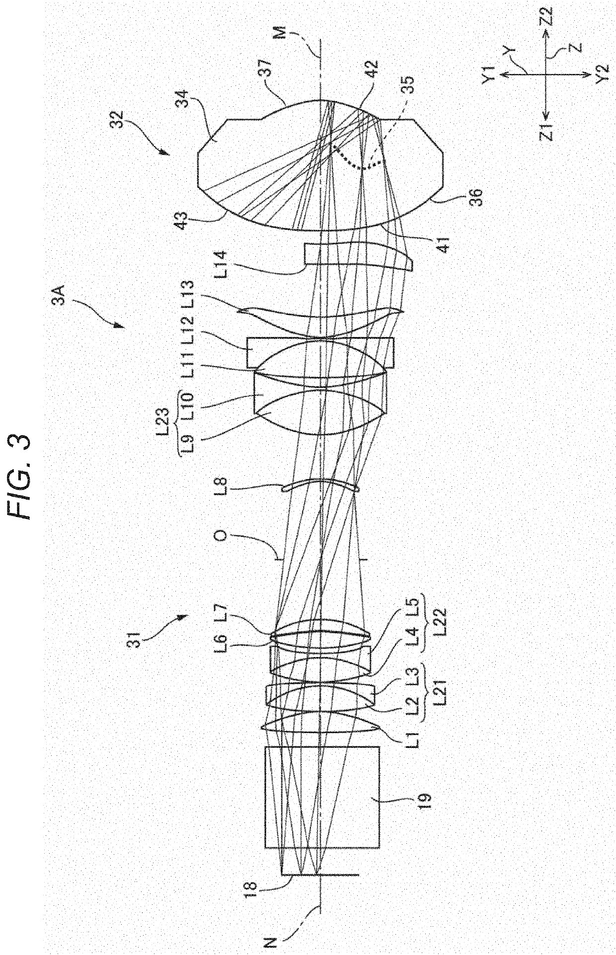
[0040]FIG. 2 is a beam diagram diagrammatically showing the entire optical system according to Example 1. FIG. 2 diagrammatically shows luminous fluxes F1 to F3, which exit out of an optical system 3A according to the present example and reach the screen S. The luminous flux F1 is a luminous flux that reaches a smallest image height position. The luminous flux F3 is a luminous flux that reaches a largest image height position. The luminous flux F2 is a luminous flux that reaches a position between the position that the luminous flux F1 reaches and the position that the luminous flux F3 reaches. FIG. 3 is a beam diagram of the optical system 3A according to Example 1. FIG. 4 is a beam diagram of the optical system 3A according to Example 1 in a case where FIG. 3 is viewed in the vertical direction. FIG. 5 is a beam diagram showing beams traveling from a lens located in a position closest to the enlargement side in a first optical system to a second optical system.

[0041]The optical sy...

example 2

[0068]FIG. 7 is a beam diagram diagrammatically showing the entire optical system according to Example 2. FIG. 7 diagrammatically shows luminous fluxes F1 to F3, which exit out of an optical system 3B according to the present example and reach the screen S. The luminous flux F1 is a luminous flux that reaches a smallest image height position. The luminous flux F3 is a luminous flux that reaches a largest image height position. The luminous flux F2 is a luminous flux that reaches a position between the position that the luminous flux F1 reaches and the position that the luminous flux F3 reaches. FIG. 8 is a beam diagram of the optical system 3B according to Example 2. FIG. 9 is a beam diagram of the second optical system.

[0069]The optical system 3B according to the present example is formed of a first optical system 31 and a second optical system 32 sequentially arranged from the reduction side toward the enlargement side, as shown in FIG. 8. The second optical system 32 is disposed ...


PUM

PropertyMeasurementUnit
transmissionaaaaaaaaaa
focal lengthaaaaaaaaaa
shapeaaaaaaaaaa

Abstract

An optical system includes a lens having a first transmission surface, a reflection surface disposed on an enlargement side of the first transmission surface, and a second transmission surface disposed on the enlargement side of the reflection surface. The lens is made of resin. The reflection surface has a concave shape. A conditional expression below is satisfied,10≤q×Fno / f2≤2989where Fno is an F-number of the optical system, f is a focal length of the optical system, and q is an amount of light in an enlargement-side conjugate plane.

Description

[0001]The present application is based on, and claims priority from JP Application Serial Number 2020-145438, filed Aug. 31, 2020, the disclosure of which is hereby incorporated by reference herein in its entirety.BACKGROUND1. Technical Field[0002]The present disclosure relates to an optical system, a projector, and an imaging apparatus.2. Related Art[0003]JP-A-2019-133061 describes a projector that magnifies and projects via a projection system a projection image formed by an image formation section. The projection system described in JP-A-2019-133061 is formed of a first optical system and a second optical system sequentially arranged from the reduction side toward the enlargement side. The first optical system is a refractive optical system including a plurality of lenses. The second optical system is a single optical element. The optical element is made of an optical material, such as glass or plastic. The optical element has a light incident surface, a reflection surface, and a...

Claims


Application Information

Patent Timeline
Patent Type & Authority Applications(United States)
IPC IPC(8): G03B21/00G03B21/20G02B13/16
CPCG03B21/006G03B21/567G02B13/16G03B21/2066G03B21/142G03B21/28G03B17/17G02B17/0812G02B17/086
Inventor YANAGISAWA, HIROTAKA
Owner SEIKO EPSON CORP
Learn More