Load weighting control apparatus

Inactive Publication Date: 2011-02-17
KASUGA HIROSHI
View PDF7 Cites 0 Cited by
  • Summary
  • Abstract
  • Description
  • Claims
  • Application Information

AI Technical Summary

Benefits of technology

[0006]The present invention was made in view of the above problems, and it is an aim of the present invention to provide a load weighting control apparatus that, by using / adopting a vacuum principle to convert an appropriate amount of force calculated by a vacuum response from a controlled object weighting load to stress at another position, suppresses deterioration of a controlled object, and furthermore, markedly reduces the amount of energy usage necessary for control, and that also has a simple structure and therefore inexpensive manufacturing costs and running costs.
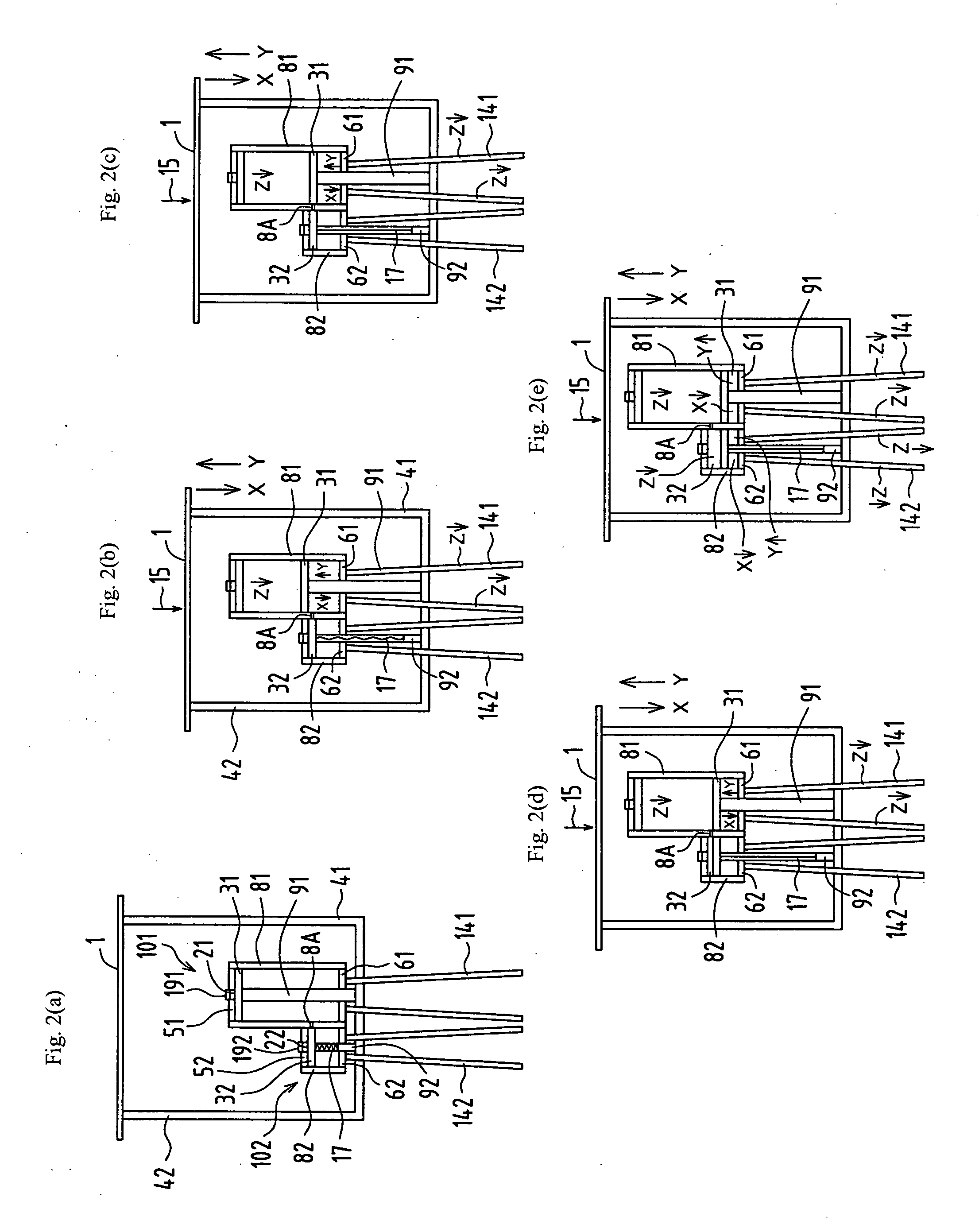
[0023]For example, when the area of the piston of the main vacuum cylinder is set to 6 square centimeters, and the area of the piston of the auxiliary vacuum cylinder is set to 4 square centimeters, the main vacuum cylinder causes control feedback from a 6 kilogram weighting load by the area of the piston of the main vacuum cylinder, and if furthermore the auxiliary vacuum cylinder causes feedback, a control force of 4 kilograms is newly added, so by combining the main vacuum cylinder and the auxiliary vacuum cylinder a total of 10 kilograms can be controlled. This indicates that the invention is very advantageous for load weighting control in a case where the load is variable. In this way, with a structure in which a shared vacuum chamber is formed and control is performed while operating the main vacuum cylinder and the auxiliary vacuum cylinder at different times, it is possible to further increase the breadth and amount of force that can be controlled, in comparison to using a single vacuum cylinder.
[0027]The load weighting control value that is converted to stress and removed from on each cylinder tube is at least the amount of the resistance load of the main vacuum cylinder, but this control value is proportional to the total piston cross-sectional area applied until immediately before the piston and the cylinder tube merge together and start to return in the overlapping direction, so the number of auxiliary vacuum cylinders that contribute to control is increased, and as the controlled object total weighting load and the total piston control value including the last auxiliary vacuum cylinder become closer in steps, the value of load weighting that is controlled increases, and furthermore, the breadth of control variation also may be reduced.
[0032]With this configuration, it is possible to provide an equivalent uniform load weighting control for 
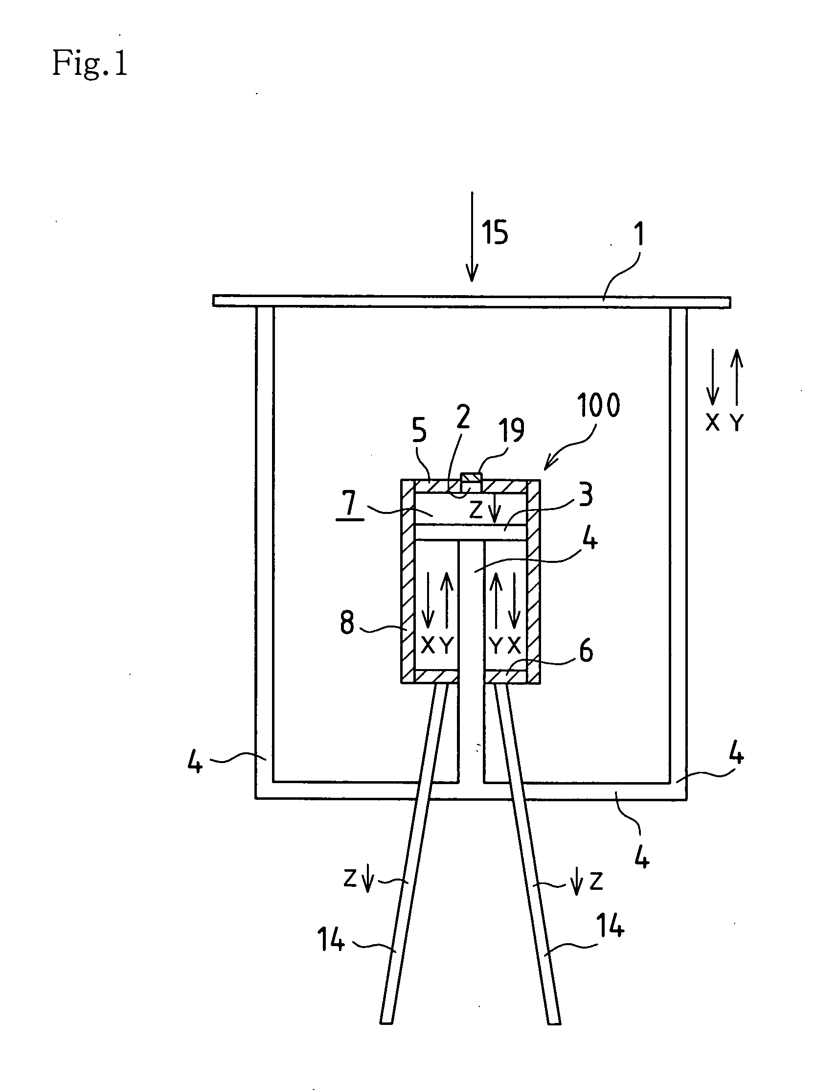
variable load weighting of a controlled object load. In vacuum response, as described above, a load corresponding to the piston cross-sectional area occurs on the piston, and this load is set in advance. Even while causing sliding of the piston and cylinder tube with a controlled object weighting load that exceeds that preset load, by intermediately restraining excessive sliding that occurs with a residual load that exceeds the preset load that has been set in advance, the set load portion that has been set in advance can be substantially controlled. As a means of doing so, a plate, bar, or other structural item may be disposed outside of the cylinder tube to block sliding. Therefore, during control, the above-described set load portion that has been set in advance from the controlled object weighting load can always be equivalently converted to stress, and thus the load on the cylinder tube can be reduced.
[0033]The shielding wall can also be utilized as a means of supplying the weighting load of the controlled object that has exceeded the vacuum load that occurred on the piston as the initial motion load of the other vacuum cylinder. As a result, a plurality of vacuum cylinders can be operated with the addition of one load weighting, and thus compound load weighting control that is applicable for many purposes is made possible.
[0034]According to the load weighting control apparatus of the present invention, a vacuum is formed using the weighting load of a controlled object itself, and a resistance load that occurs as a result acts as a counteraction on the controlled object, so the weighting load of the controlled object on the plate can be substantially set to approximately zero, and further, without moving the controlled object, load weighting control can be variously performed by converting, to stress at another position, a vacuum chamber load portion equivalent to a resistance load portion that corresponds to the vacuum load produced by the piston from the weighting load. In addition, energy is not needed for this. As a result, energy conservation can be realized, and manufacturing costs can be suppressed to a low level.

Problems solved by technology

However, in the above technology, there is a limit to the range of effects obtained according to the aims of that technology.

Method used


Image

  • Load weighting control apparatus
  • Load weighting control apparatus
  • Load weighting control apparatus

Examples


Embodiment Construction

[0042]First, in the present embodiment, a vacuum cylinder shown in FIGS. 6 and 7 is applied, and this structure is adopted as a basic principle.

[0043]FIG. 1 is a cross-sectional view that shows a configuration related to a load weighting control apparatus of the present invention, and shows a state in which the load weighting control apparatus has been placed on the floor.

[0044]A single vacuum cylinder 100 is used in this apparatus. The vacuum cylinder 100 is provided with a cylinder tube 8, end walls 5 and 6 that respectively close both ends of the cylinder tube 8, an air vent 2 that passes through the one end wall 5 and is used to discharge air within the cylinder tube 8 to the outside, a valve 19 that is provided in the air vent 2 and is used to open / tightly close the atmosphere within the cylinder tube 8 to the outside, a piston 3 that slides back and forth within the cylinder tube 8, and a piston rod 4 that is linked to the piston 3 and is provided passing through the other end...


PUM


Abstract

A load weighting control apparatus that suppresses deterioration of a controlled object due to impacts or the like during control, and for which energy usage costs required for control are markedly reduced, and that has a simple structure and therefore inexpensive manufacturing costs and running costs. The apparatus includes a main vacuum cylinder provided with a cylinder tube, end walls, an air vent that passes through one end wall, a valve that is provided in the air vent and serves to open / tightly close the atmosphere inside of the cylinder tube to the outside, a piston that slides back and forth within the cylinder tube, and a piston rod that is linked to the piston and passes through the other end wall and an auxiliary vacuum cylinder that includes a slacking portion where a piston rod produces slackness in the main vacuum cylinder.

Description

BACKGROUND OF THE INVENTION[0001]The present invention relates to a load weighting control apparatus that controls a weighting load applied to an object.[0002]Conventional technology for performing load weighting control centers mainly on configurations employing impact absorption or mitigation, in which a spring, oil pressure, or air is used. A major aim of the conventional technology is maintenance of the shape of a controlled object and maintaining and insuring balance by mitigating an impact.[0003]Also, as disclosed in JP 3934215B, there is a vacuum cylinder in which vacuum suction force is used as an attractive or suction load of a controlled object. FIG. 6 is a cross-sectional view that shows such a vacuum cylinder, and shows a state in which a piston has been pulled upward to form a vacuum chamber. FIG. 7 shows a state in which the piston has been closely fitted to a lower end wall.[0004]A vacuum cylinder 100 is provided with a cylinder main body configured from a cylinder tu...

Claims


Application Information

Patent Timeline
IPC IPC(8): F16F9/00
CPCF16F9/3221F16F9/0218
Inventor KASUGA, HIROSHI
Owner KASUGA HIROSHI
Why Eureka
Try Eureka