Method for waking from energy-efficient hibernation

Active Publication Date: 2021-10-07
TRAKPOINT SOLUTIONS INC
View PDF0 Cites 0 Cited by
  • Summary
  • Abstract
  • Description
  • Claims
  • Application Information

AI Technical Summary

Benefits of technology

The present invention provides different methods for RF tags based on whether they are receiving or sending transmissions. The receiving tag uses a precise clock to track down a beacon from its associated device and synchronize its own clock. The tag then saves power by remaining in a hibernation state until the next awakening time. The sent tag uses a sloppy clock to transmit a beacon to its associated device, which then delays its timing for future transmissions. The tag saves power by being in a hibernation state until the next awakening time. The invention also utilizes a recipient array format that counterintuitively improves energy efficiency by balancing the energy used to transmit the array. Overall, the invention offers a more energy-efficient and accurate approach for RF tags.

Problems solved by technology

This limits energy efficiency due to the frequent transmissions taking place between members of the system.
While these systems improve energy efficiency when compared to prior systems and maintain a high level of accuracy, they are limited by the fact that the tags must always be prepared to receive a wakeup signal and that every RF tag must be kept active after receiving a wakeup signal.

Method used


Image

  • Method for waking from energy-efficient hibernation
  • Method for waking from energy-efficient hibernation
  • Method for waking from energy-efficient hibernation

Examples


example

[0089]The following is a non-limiting example of the present invention. It is to be understood that said example is not intended to limit the present invention in any way. Equivalents or substitutes are within the scope of the present invention.

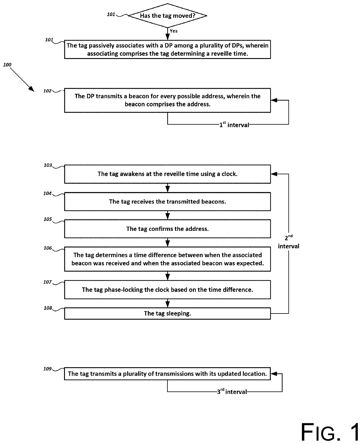
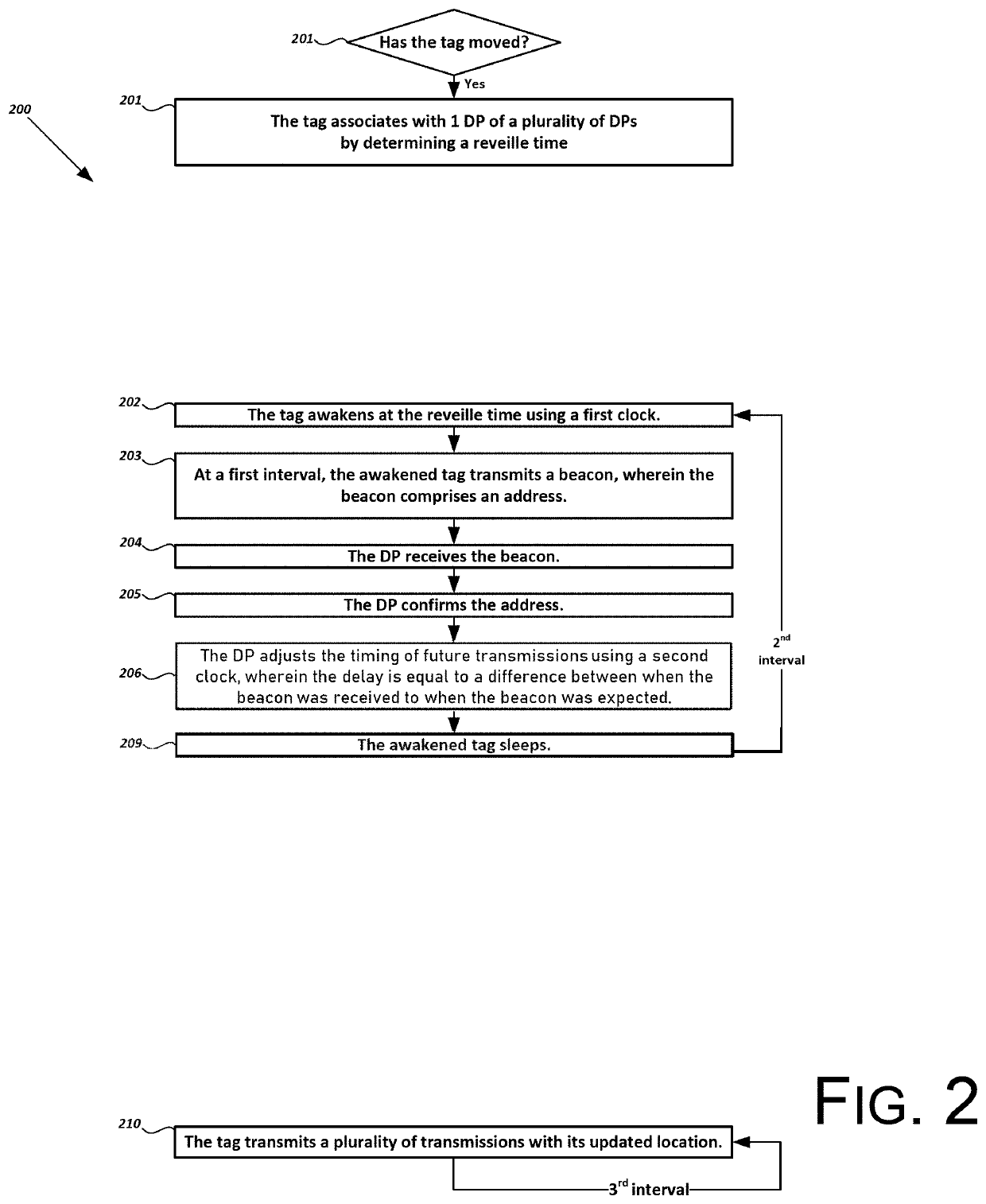
[0090]Referring to FIG. 6, a specific embodiment of the present invention features a method (600) of waking from energy-efficient hibernation to transmit an indoor localization beacon by initiating a WakeUp subroutine. The method may comprise a tag (1001) passively associating (601) with a detection point (DP) (1002) of a plurality of DPs if the tag (1001) has moved to a new location. The procedure for associating may comprise the tag (1001) determining a reveille time to transmit a beacon addressed to the DP (1002). The reveille time may be equal to at least one of a concatenation or hash of a tag ID and a DP ID, a geographic number, a location ID of a DP (1002) modified by a location ID of a tag (1001), or a combination thereof. The method ...


PUM


Abstract

The present invention is directed to energy-efficient hibernation in indoor wireless localization systems. A tag passively associates with a detection point (DP) and establishes a reveille time. The tag will awaken at the reveille time and send or receive a beacon to or from its associated DP. If the tag is receiving a beacon, it will awaken, receive, phase-lock its clock based on when the beacon was expected and when it was actually received, and return to hibernation. The DP transmits a scattershot of beacons, one for every tag in the system. If the tag is sending a beacon, it will awaken, send its beacon, and return to hibernation. The DP will receive the beacon and adjust its own clock based on the delay between when the beacon was expected and when it was actually received. The tag will broadcast its location to the DP on a set interval.

Description

CROSS-REFERENCES TO RELATED APPLICATIONS[0001]This application is a continuation-in-part and claims benefit of U.S. patent application Ser. No. 17 / 065,197, filed Oct. 7, 2020 which is a continuation-in-part and claims benefit of U.S. patent application Ser. No. 16 / 778,577, filed Jan. 31, 2020 (now U.S. Pat. No. 10,841,894), the specification of which is incorporated herein in its entirety by reference.BACKGROUND OF THE INVENTION[0002]For indoor localization systems comprising a plurality of radiofrequency (RF) tags and a plurality of detection points (DP), a balanced trade-off between energy-efficiency and accuracy is a primary design objective. Past indoor localization systems strove to maximize accuracy by keeping RF tags in an active state for the sake of updating the tags and DPs on each other's locations often. This limits energy efficiency due to the frequent transmissions taking place between members of the system. Research found that RF tags can switch between an active and ...

Claims


Application Information

Patent Timeline
IPC IPC(8): H04W52/02H04W12/06G01S3/14
CPCH04W52/0216G01S3/14H04W12/06H04W52/0229H04L9/3273H04L2209/805Y02D30/70G01S1/0428G01S1/045G01S5/02G06F9/4401
Inventor SIANN, JONWILLIAMS, CHRISTOPHER
Owner TRAKPOINT SOLUTIONS INC
Why Eureka
Try Eureka