Rubber vulcanizer and rubber vulcanizing method

Inactive Publication Date: 2015-01-22
JTEKT CORP
View PDF5 Cites 0 Cited by
  • Summary
  • Abstract
  • Description
  • Claims
  • Application Information

AI Technical Summary

Benefits of technology

The invention provides a rubber vulcanizer and a method that can flexibly handle changes in the number of rubber products being made, reducing manufacturing costs and increasing productivity.

Problems solved by technology

According to the conventional rubber vulcanizing method, only two rubber products are molded during one vulcanization, and thus the productivity is low.
Thus, a great initial investment is required.
Therefore, if production of the rubber products is discontinued, excessive losses are caused.
Further, with the vulcanizer, it is not easy to flexibly cope with variations in the number of rubber products to be manufactured, so that it is difficult to recoup an initial investment if the number of products to be manufactured varies.
Thus, it is not easy to suppress manufacturing costs and to enhance the productivity.

Method used


Image

  • Rubber vulcanizer and rubber vulcanizing method
  • Rubber vulcanizer and rubber vulcanizing method
  • Rubber vulcanizer and rubber vulcanizing method

Examples


Embodiment Construction

[0022]Hereinafter, example embodiments of the invention will be described with reference to the accompanying drawings.

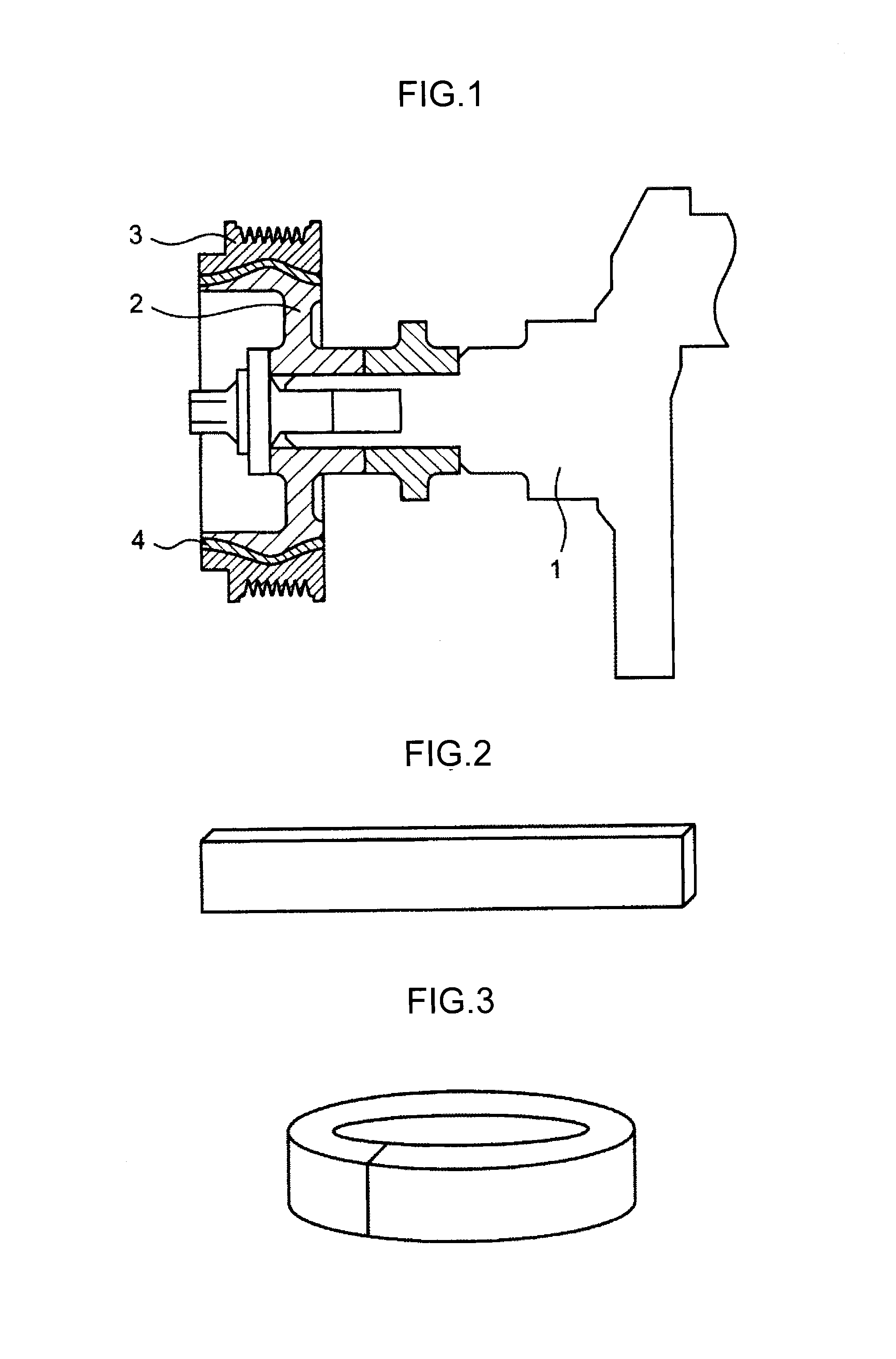
[0023]FIG. 1 is a schematic sectional view illustrating a damper pulley provided with a rubber damper 4 that is manufactured by a rubber vulcanizer according to an embodiment of the invention.

[0024]The damper pulley is fitted on a crankshaft 1. The damper pulley includes an annular hub 2, an annular pulley mass 3 and the rubber damper 4. The rubber damper 4 is disposed between an outer peripheral face of the hub 2 and an inner peripheral face of the pulley mass 3. A rubber strip illustrated in FIG. 2, which is formed through vulcanization performed by the rubber vulcanizer, is rounded as illustrated in FIG. 3, and then press-fitted between the hub 2 and the pulley mass 3. In this way, the rubber damper 4 is formed.

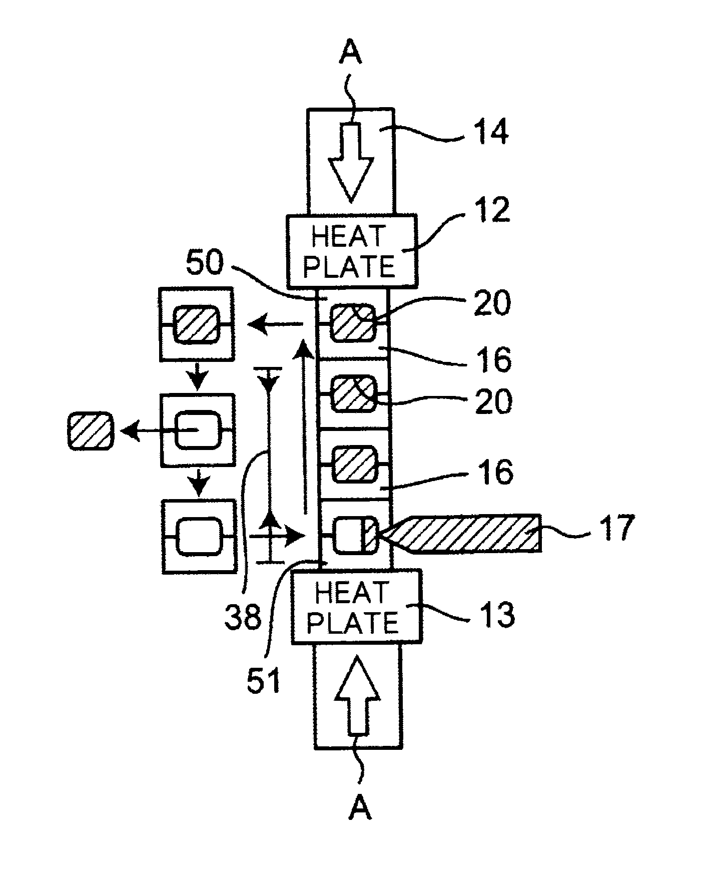
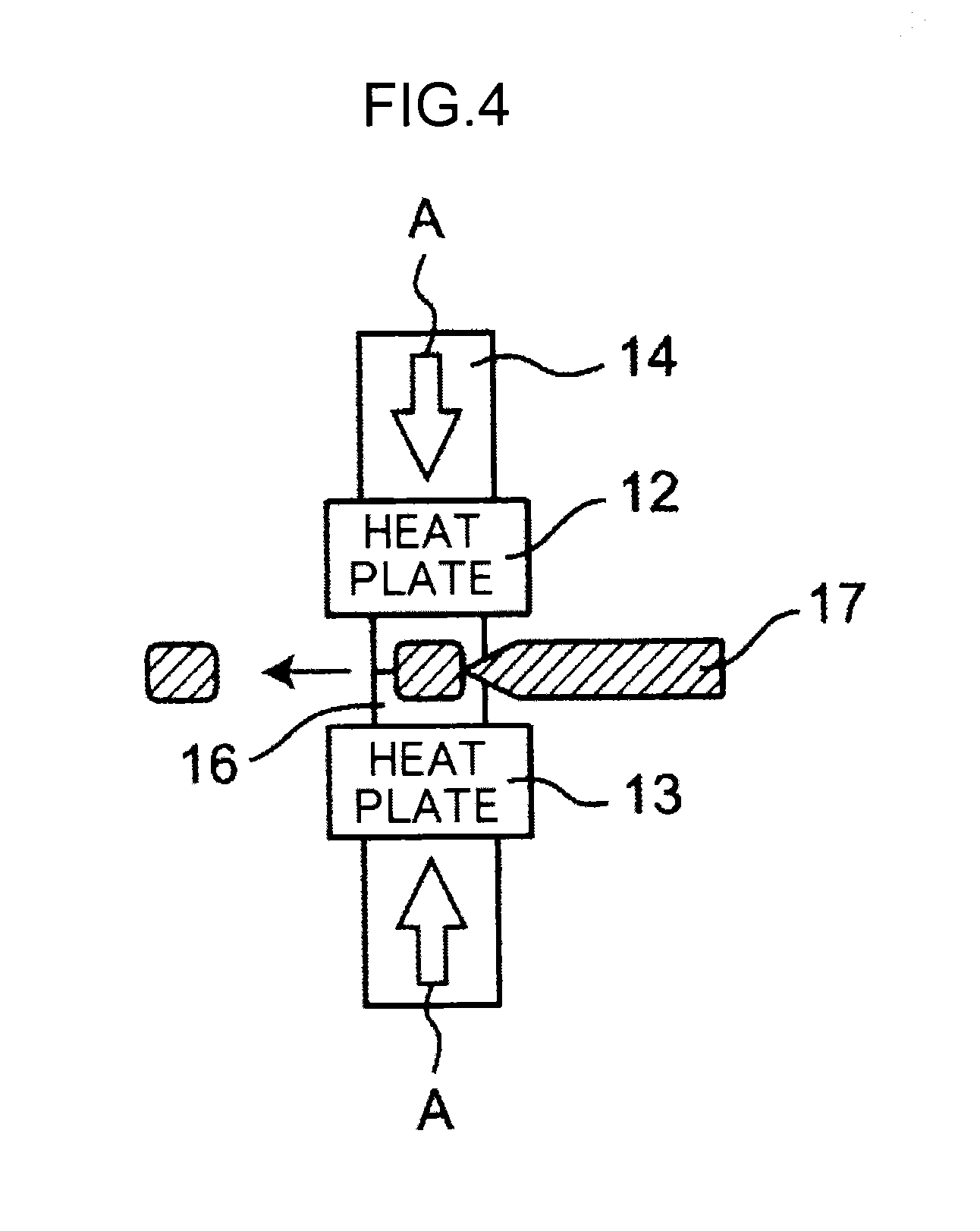
[0025]FIG. 4, FIG. 5 and FIG. 6 are schematic views that illustrate the rubber vulcanizer in the embodiment of the invention, which is used to manufacture ...


PUM

PropertyMeasurementUnit
Forceaaaaaaaaaa

Abstract

A rubber vulcanizer includes: a pair of heat plates disposed to be opposed to each other in a prescribed direction and to be apart from each other in the prescribed direction; and one or more dies for rubber molding stacked on each other in the prescribed direction between the heat plates. The rubber vulcanizer is able to realize either a state in which the dies of which the number is N are stacked on each other in the prescribed direction between the heat plates, or a state in which the dies of which the number is (N+1) are stacked on each other in the prescribed direction between the heat plates, where N is a natural number that satisfies at least a condition that 1≦N≦M, and M is a certain positive integer.

Description

INCORPORATION BY REFERENCE[0001]The disclosure of Japanese Patent Application No. 2013-149503 filed on Jul. 18, 20013 including the specification, drawings and abstract is incorporated herein by reference in its entirety.BACKGROUND OF THE INVENTION[0002]1. Field of the Invention[0003]The invention relates to a rubber vulcanizer and a rubber vulcanizing method. The invention is applicable to manufacturing of any products made of rubber that is vulcanized in dies. The invention is suitably applicable to manufacturing of, for example, an annular or strip-shaped rubber product used for a damper pulley that is fitted[0004]2. Description of the Related Art[0005]Japanese Utility Model Application Publication No. 63-88416 describes an example of a conventional rubber vulcanizer (FIG. 1). The vulcanizer includes an upper die and a lower die. Each of the upper die and the lower die has two recesses. The recesses of the upper die and the recesses of the lower die define rubber molding cavities...

Claims


Application Information

Patent Timeline
IPC IPC(8): B29C35/02
CPCB29K2007/00B29C35/02B29C33/0022B29C33/0088B29C33/02B29D99/0032B29K2021/00
Inventor HAMADA, KAZUKIUSUKI, ISAO
Owner JTEKT CORP
Why Eureka
Try Eureka