Semiconductor integrated circuit including constant adjusting circuit

Inactive Publication Date: 2011-09-15
RENESAS ELECTRONICS CORP
View PDF12 Cites 3 Cited by
  • Summary
  • Abstract
  • Description
  • Claims
  • Application Information

AI Technical Summary

Benefits of technology

[0027]In the time constant adjusting circuit according to Patent Literature 1, it is necessary to prepare the time constant generating circuit for reference. The area of a semiconductor chip is increased for the area of the time constant generating circuit. In addition, in the time constant adjusting circuit according to Patent Literature 1, a large-scale circuit which is exclusively used for adjusting a variation of the time constant by using a fine resolution is prepared, thereby resulting in an increase in the layout of an integrated circuit. For these reasons, the time constant adjusting circuit according to Patent Literature 1 is accompanied by increased manufacturing costs.
[0030]In a time constant adjusting circuit according to the present invention, by using a switched capacitor, sufficient accuracy is maintained even in a state that a time constant generating circuit is incorporated in an integrated circuit. A storage section for storing a correction result of the time constant is further arranged so that the time constant adjusting circuit and a normal operation circuit after time constant adjustment can be partially used in common. The number of terminals of the integrated circuit and an area of a semiconductor chip can be saved, and it is therefore possible to suppress a manufacturing cost. Furthermore, as long as a power supply is supplied from the outside, the time constant can be adjusted automatically and autonomously.

Problems solved by technology

For these reasons, the time constant adjusting circuit according to Patent Literature 1 is accompanied by increased manufacturing costs.

Method used


Image

  • Semiconductor integrated circuit including constant adjusting circuit
  • Semiconductor integrated circuit including constant adjusting circuit
  • Semiconductor integrated circuit including constant adjusting circuit

Examples


first embodiment

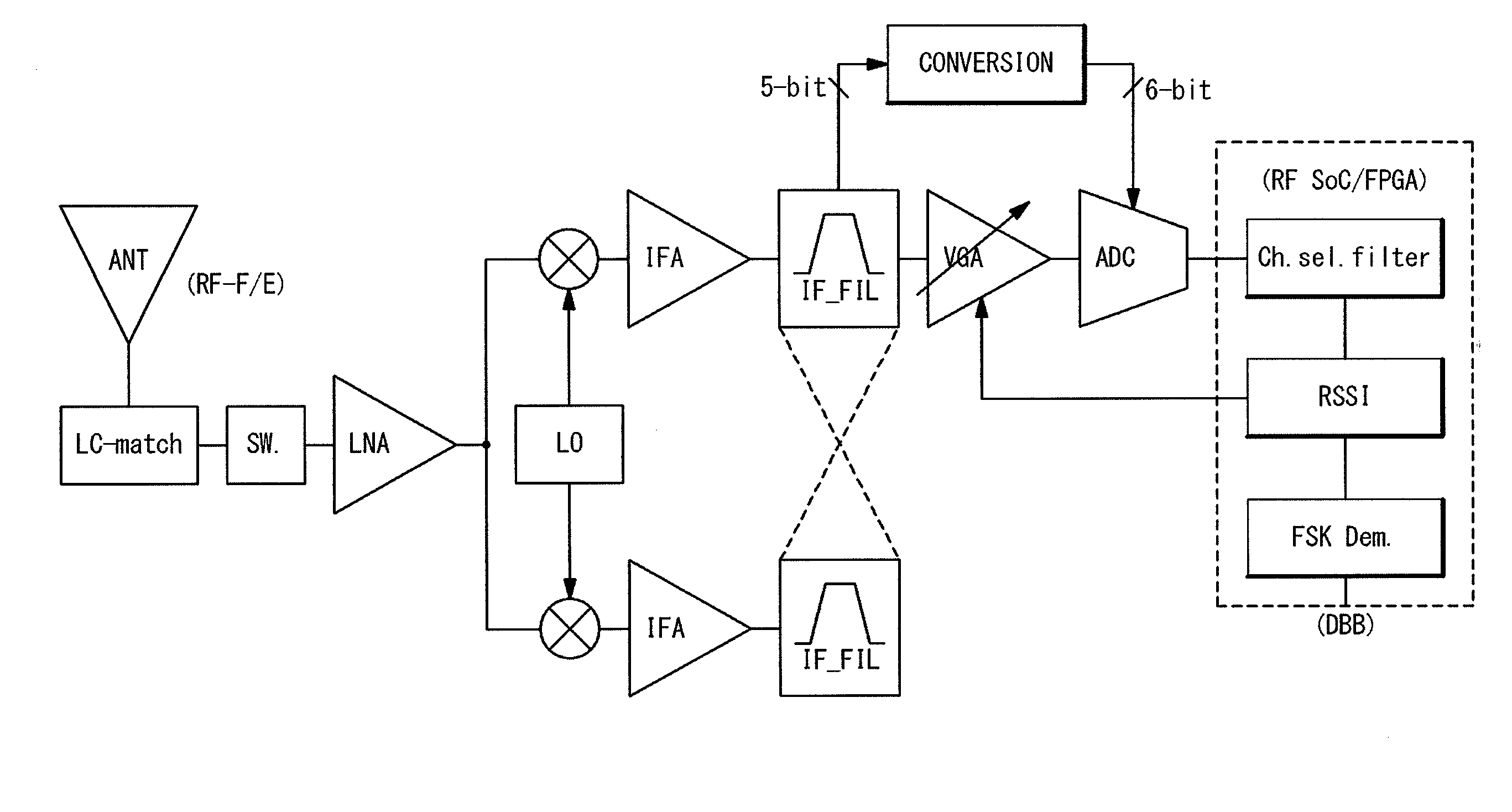
[0045]FIG. 4 is a block diagram schematically showing a configuration of an electronic circuit which uses the time constant adjusting circuit according to a first embodiment of the present invention. The electronic circuit is provided with an antenna section (ANT), a low noise amplifier circuit section (LNA), mixer circuit sections, complex band-pass filter sections (IF_FIL), a variable gain amplifier circuit section (VGA), an analog-to-digital converter (ADC), and a digital baseband circuit section (DBB).

[0046]A radio signal is received by the antenna (ANT) through an LC impedance matching circuit (LC-match). The low noise amplifier circuit section (LNA) is arranged at a rear stage of the antenna section ANT, and the received signal is supplied to the low noise amplifier circuit section (LNA) through a switch (SW) and amplified by it. Each of the mixer circuit sections is arranged at a rear stage of the low noise amplifier circuit section (LNA). Orthogonal signals are generated by ...


PUM


Abstract

A semiconductor integrated circuit includes an integrating circuit comprising a variable resistance, an integration capacitance and an amplifier; a switched capacitor connected with the amplifier in parallel to the variable resistance; and an adjusting circuit configured to adjust a resistance value of the variable resistance. The integrating circuit generates a control signal of a voltage based on a first time constant determined based on the resistance value of the variable resistance and a capacitance value of the integration capacitance, and a second time constant determined based on a capacitance value of the switched capacitor and the capacitance value of the integration capacitance. The adjusting circuit adjusts the resistance value of the variable resistance based on the control signal.

Description

INCORPORATION BY REFERENCE[0001]This patent application claims a priority on convention based on Japanese Patent Application No. 2010-51, 618 filed on Mar. 9, 2010. The disclosure thereof is incorporated herein by reference.TECHNICAL FIELD[0002]The present invention relates to a time constant adjusting circuit and a time constant adjustment method using the same, and in particular relates to a time constant adjusting circuit having a variable resistance and a time constant adjustment method using the same.[0003]A value RC as a product of a value of a resistance R and a value of a capacitance C is called a time constant. The time constant is used for a method of setting a cut-off frequency of a filter, and a larger time constant is associated with a longer period of time. By setting optional values of the resistance R and the capacitance C, the time constant can be set in the circuit.[0004]Here, variations in the values of the resistance R and the capacitance C are directly related t...

Claims


Application Information

Patent Timeline
IPC IPC(8): G06G7/184
CPCH03H19/004H03H11/1291
Inventor OKA, YOSHITAKA
Owner RENESAS ELECTRONICS CORP
Why Eureka
Try Eureka