Supercharge Your Innovation With Domain-Expert AI Agents!

Power failure detection device and method

a technology of power failure and detection device, which is applied in the direction of emergency power supply arrangement, alarms, instruments, etc., can solve the problems of increasing the volume of the whole device, increasing production costs, and failing to transmit specific packets by the user terminal

Active Publication Date: 2022-03-03
REALTEK SEMICON CORP
View PDF8 Cites 0 Cited by
  • Summary
  • Abstract
  • Description
  • Claims
  • Application Information

AI Technical Summary

Benefits of technology

The present invention provides a power failure detection device and method that solves the problems of prior art. The device includes a voltage reduction circuit, a detection voltage generating circuit, a detection circuit, and a transmitting circuit. The voltage reduction circuit generates an output voltage lower than the input voltage, which is generated by an active electronic component. The detection voltage generating circuit generates a detection voltage lower than the output voltage and higher than the voltage of a low voltage terminal. The detection circuit generates a detection result based on the detection voltage and a trigger voltage. The transmitting circuit sends a power failure alert to a far-end device when the detection result indicates that the detection voltage is lower than the trigger voltage. This device allows for timely detection of power failures and prevents damage to equipment or personnel.

Problems solved by technology

In normal circumstances, the above-mentioned input voltage is a 12 volts (12V) DC voltage; however, an integrated circuit (IC) for the detection of the division voltage in the user terminal cannot withstand an excessively high voltage, and thus the division voltage is usually lower than 3.3V.
In light of the above, the hold time (i.e., the duration from the time point of the division voltage being lower than the trigger voltage to the time point of the user terminal being incapable of normal operation) is very short, and if the hold time is too short, the user terminal will fail to transmit the specific packet.
However, the above-mentioned solution requires a larger PCB for the setting of the capacitor, and this not only increases the volume the whole device, which is disadvantageous to the miniaturization of the device, but also increases the production cost.

Method used


Image

  • Power failure detection device and method
  • Power failure detection device and method
  • Power failure detection device and method

Examples


Embodiment Construction

[0015]The present disclosure discusses a power failure detection device and method. The device and method are applicable to a user terminal and can increase the hold time of a dying gasp function.

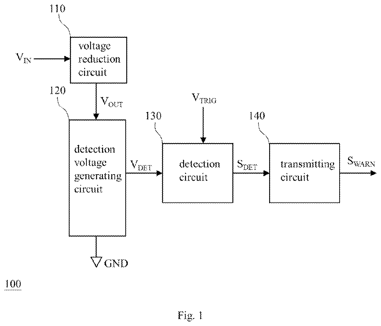
[0016]FIG. 1 shows an embodiment of the power failure detection device of the present disclosure. The power failure detection device 100 of FIG. 1 includes a voltage reduction circuit 110, a detection voltage generating circuit 120, a detection circuit 130, and a transmitting circuit 140. The voltage reduction circuit 110 is or includes at least one active electronic component (e.g., at least one diode), and is configured to generate an output voltage (VOUT) according to an input voltage (VIN), wherein the output voltage is lower than the input voltage; for example, the output voltage is lower than a half of the input voltage. The detection voltage generating circuit 120 is coupled between the voltage reduction circuit 110 and a low voltage terminal (GND) (e.g., a ground terminal), and conf...


PUM


Abstract

Disclosed is a power failure detection device and method capable of issuing a power failure alert early. The device includes a voltage reduction circuit, a detection voltage generating circuit, a detection circuit, and a transmitting circuit. The voltage reduction circuit is or includes at least one active electronic component, and generates an output voltage according to an input voltage higher than the output voltage. The detection voltage generating circuit is coupled between the voltage reduction circuit and a low voltage terminal, and generates a detection voltage according to the output voltage that is between the output voltage and the voltage of the low voltage terminal. The detection circuit generates a detection result according to the detection voltage and a trigger voltage. The transmitting circuit sends a power failure alert to a far-end device on condition that the detection result indicates that the detection voltage is lower than the trigger voltage.

Description

BACKGROUND OF THE INVENTION1. Field of the Invention[0001]The present disclosure relates to a detection device and method, especially to a power failure detection device and method.2. Description of Related Art[0002]A dying gasp function allows a user terminal to have enough time to transmit a specific packet to a server terminal after power failure, and thus the server terminal can learn that the cause of the disconnection is power failure rather than problems of communication lines.[0003]The current dying gasp function is established in the following manner: a user terminal generating a division voltage of an input voltage with a resistor-type voltage divider (e.g., a 3.22KΩ resistor and a 499Ω resistor connected in series); and the user terminal transmitting a specific packet to a server terminal when the division voltage is lower than a trigger voltage, and stopping transmitting the specific packet when the division voltage is higher than a de-trigger voltage. In normal circumst...

Claims


Application Information

Patent Timeline
Patent Type & Authority Applications(United States)
IPC IPC(8): G08B21/18H02J9/06G01R19/165
CPCG08B21/185G01R19/1659G08B21/182H02J9/061G01R19/16538H02J3/0012
Inventor WANG, CHIA-LUNGHUANG, MIN-HUNGLI, CHIEN-YI
Owner REALTEK SEMICON CORP
Features
  • R&D
  • Intellectual Property
  • Life Sciences
  • Materials
  • Tech Scout
  • Unparalleled Data Quality
  • Higher Quality Content
  • 60% Fewer Hallucinations
Learn More