Display apparatus

a technology of display apparatus and display screen, which is applied in the direction of electrical apparatus, basic electric elements, and semiconductor devices, can solve the problems that the display screen may be disadvantageously vulnerable to moisture and oxygen, and achieve the effects of ensuring the reliability of the display screen, preventing or inhibiting the permeation of moisture, and ensuring the life of the produ

Pending Publication Date: 2022-03-10
LG DISPLAY CO LTD
View PDF0 Cites 0 Cited by
  • Summary
  • Abstract
  • Description
  • Claims
  • Application Information

AI Technical Summary

Benefits of technology

[0013]According to some embodiments of the present disclosure, it is possible to inhibit or prevent moisture from permeating into the display area from the outside, thereby ensuring reliability of the display apparatus and ensuring the lifespan of the product.
[0014]According to some embodiments of the present disclosure, it is possible to inhibit or prevent the permeation of moisture without changing the mask and the process, thereby improving the process properties and manufacturing efficiency.

Problems solved by technology

However, the electroluminescent display apparatus may be disadvantageously vulnerable to moisture and oxygen.

Method used


Image

  • Display apparatus
  • Display apparatus
  • Display apparatus

Examples


first embodiment

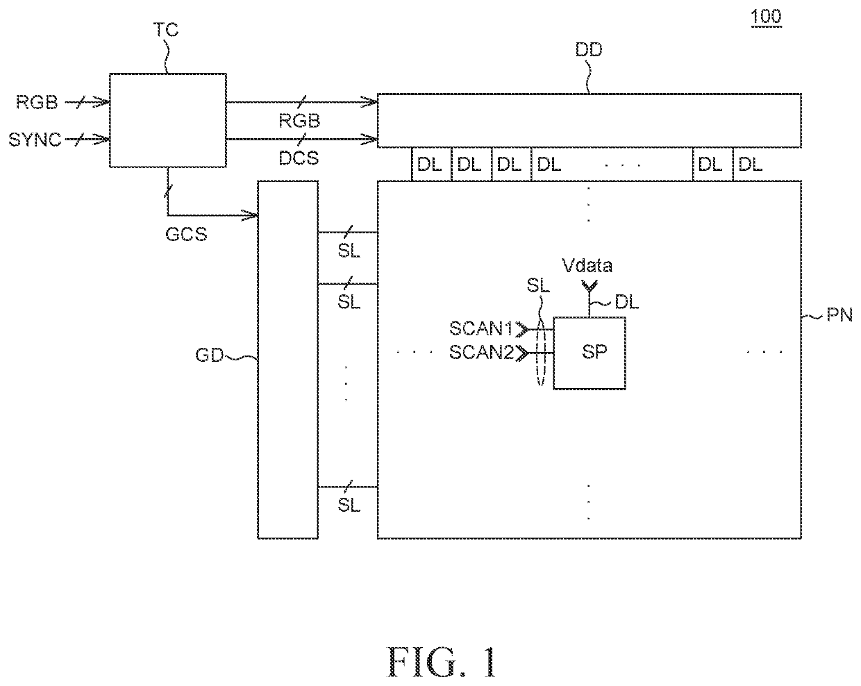
[0052]FIG. 1 is a configuration view of a display apparatus according to the present disclosure. All the components of each display apparatus according to all embodiments of the present disclosure are operatively coupled and configured.

[0053]Particularly, FIG. 1 illustrates a display panel PN, a gate driver GD, a data driver DD, and a timing controller TC, among various components of a display apparatus 100. However, embodiments of the present disclosure are not limited thereto.

[0054]With reference to FIG. 1, the display apparatus 100 can include the display panel PN including a plurality of subpixels SP, the gate driver GD and the data driver DD configured to supply various types of signals to the display panel PN, and the timing controller TC configured to control the gate driver GD and the data driver DD.

[0055]The gate driver GD can supply a plurality of scan signals to a plurality of scan lines SL based on a plurality of gate control signals GCS provided from the timing controll...

second embodiment

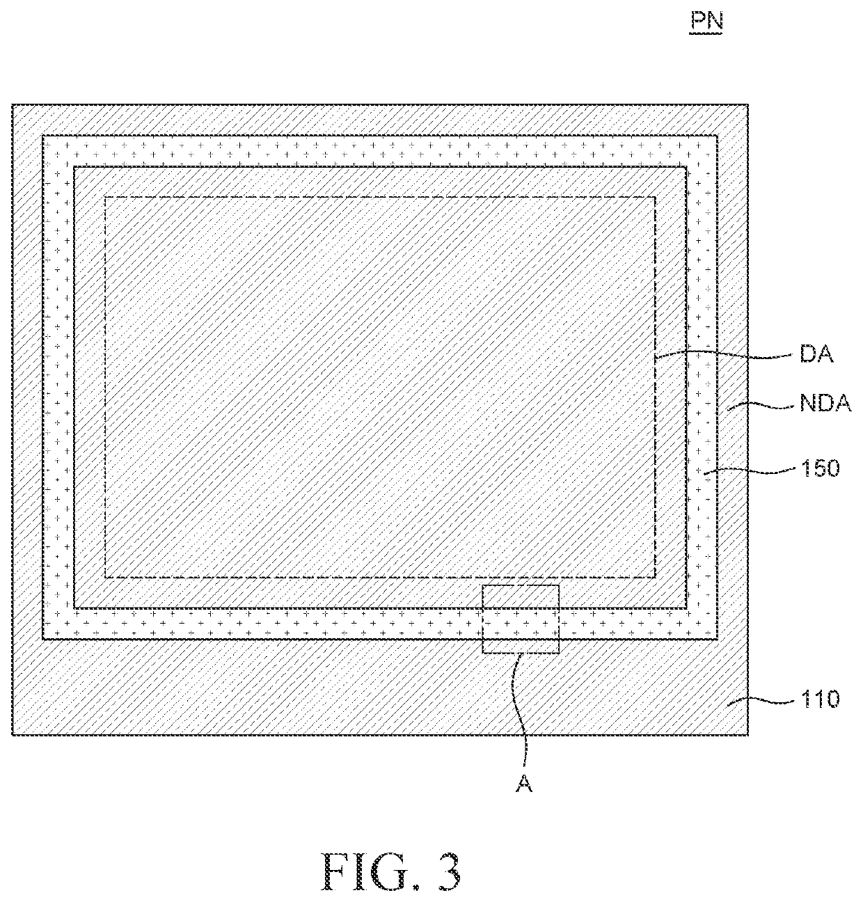
[0159]FIG. 6 is a top plan view of a display panel according to the present disclosure.

[0160]FIG. 7A is a cross-sectional view illustrating a part of a display area of the display panel illustrated in FIG. 6.

[0161]FIG. 7B is a top plan view illustrating enlarged part B of the display panel illustrated in FIG. 6.

[0162]FIG. 8A is a cross-sectional view taken along line B-B′ in FIG. 7B.

[0163]FIG. 8B is a cross-sectional view taken along line D-D′ in FIG. 7B.

[0164]FIG. 8C is a cross-sectional view taken along line E-E′ in FIG. 7B.

[0165]FIG. 8D is a cross-sectional view taken along line F-F′ in FIG. 7B.

[0166]With reference to FIGS. 6, 7A, 7B, 8A, 8B, 8C, and 8D, in the second embodiment of the present disclosure, second and third layers 235 and 236 are disposed to cover lateral surfaces of third upper and lower insulating layers 217 and 218 in first and second holes T1 and T2 (e.g., a type of double trench or stacked trenches). For example, the first and second holes T1 and T2 can form t...

third embodiment

[0270]FIGS. 9A and 9B are views illustrating a part of a cross section of a display panel of a display apparatus according to the present disclosure.

[0271]The display apparatus illustrated in FIGS. 9A and 9B is different from the display apparatus illustrated in FIGS. 7A and 7B in terms of a configuration of the substrate, and the other components of the two apparatuses are substantially identical (e.g., FIG. 9A shows a double layered substrate having multiple buffer layers). Therefore, the repetitive descriptions of the identical configurations will be omitted.

[0272]With reference to FIGS. 9A and 9B, the display apparatus according to the third embodiment of the present disclosure can include a first substrate 310a, a second substrate 310b, and a lower second buffer layer 311b provided between the first substrate 310a and the second substrate 310b.

[0273]The first substrate 310a and the second substrate 310b are support members for supporting other components of the display apparat...


PUM

PropertyMeasurementUnit
DAaaaaaaaaaa
DAaaaaaaaaaa
DAaaaaaaaaaa

Abstract

A display apparatus can include a substrate comprising a plurality of subpixels, a display area, and anon-display area; a first insulating layer disposed on the substrate; a plurality of first electrodes disposed on the first insulating layer and disposed at the plurality of subpixels, respectively; a bank disposed between the plurality of subpixels; a hole configured to divide the first insulating layer into an inner first insulating layer portion and an outer first insulating layer portion in the non-display area at a periphery of the display area, the inner first insulating layer portion being closer to the display area than the outer first insulating layer portion; a first layer disposed under the hole between the inner first insulating layer portion and the outer first insulating layer portion; and an organic layer and a second electrode disposed on the plurality of first electrodes.

Description

CROSS-REFERENCE TO RELATED APPLICATIONS[0001]This application claims the benefit of priority to Korean Patent Application No. 10-2020-0112923 filed on Sep. 4, 2020, in the Republic of Korea, the entirety of which is incorporated herein by reference into the present application.BACKGROUNDTechnical Field[0002]The present disclosure relates to a display apparatus, and more particularly, to a display apparatus capable of inhibiting or preventing moisture from permeating into a display area.Description of the Related Art[0003]Recently, display apparatuses, which visually display electrical information signals, are being rapidly developed in accordance with the full-fledged entry into the information era. Various studies are being continuously conducted to develop a variety of display apparatuses which are thin and lightweight, consume low power, and have improved performance.[0004]Among the various display apparatuses, an electroluminescent display apparatus (e.g., an OLED display) refer...

Claims


Application Information

Patent Timeline
Patent Type & Authority Applications(United States)
IPC IPC(8): H01L27/32
CPCH01L27/3258H01L27/3246H01L27/1225H01L27/3276H01L27/3262H01L27/1248H01L29/7869H10K59/124H10K59/1213H10K59/122H10K59/131H10K50/844H01L27/1218H01L27/124H01L29/78675
Inventor SHIN, HYUNGIKANG, HEEKWANG
Owner LG DISPLAY CO LTD
Why Eureka
Try Eureka