Transmission line substrate and electronic device

Pending Publication Date: 2022-03-10
MURATA MFG CO LTD
View PDF0 Cites 0 Cited by
  • Summary
  • Abstract
  • Description
  • Claims
  • Application Information

AI Technical Summary

Benefits of technology

[0009]According to the configurations described above, the first ground conductor, having a relatively low conductor ratio, is disposed on the mounting surface (first main surface) side, and the second ground conductor, having a relatively high conductor ratio, is disposed on the top surface (second main surface) side. Therefore, compared with the case in which the first ground conductor, having a relatively low conductor ratio, is positioned on the top surface side, the effect of external noise (especially, from the second main surface side) on the transmission line (signal line) is able to be reduced or prevented. This configuration also causes unwanted radio-frequency emission from the transmission line to be reduced or prevented.
[0010]According to the configurations described above, the at least one first conductor-non-formed portion is in th

Problems solved by technology

However, when the transmission line substrate, having the configuration described above, is incorporated in an electronic device (when the transmission line substrate is mounted on a circuit substrat

Method used


Image

  • Transmission line substrate and electronic device
  • Transmission line substrate and electronic device
  • Transmission line substrate and electronic device

Examples


first preferred embodiment

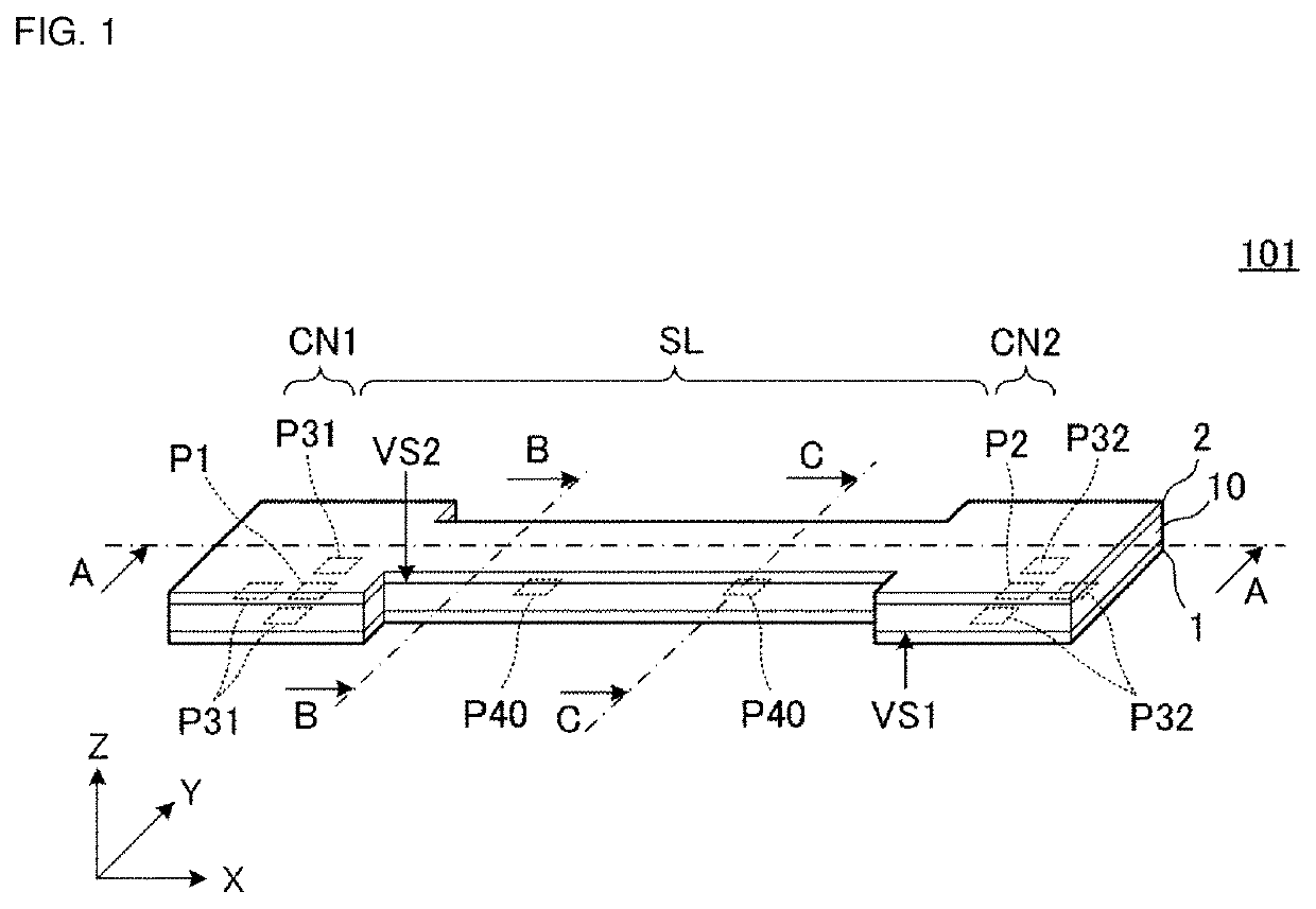
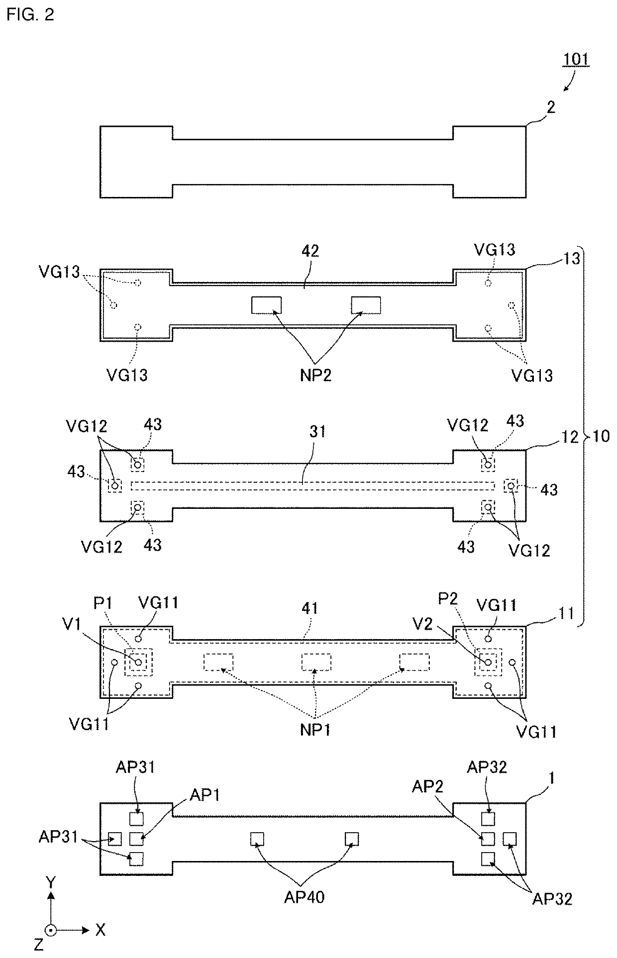
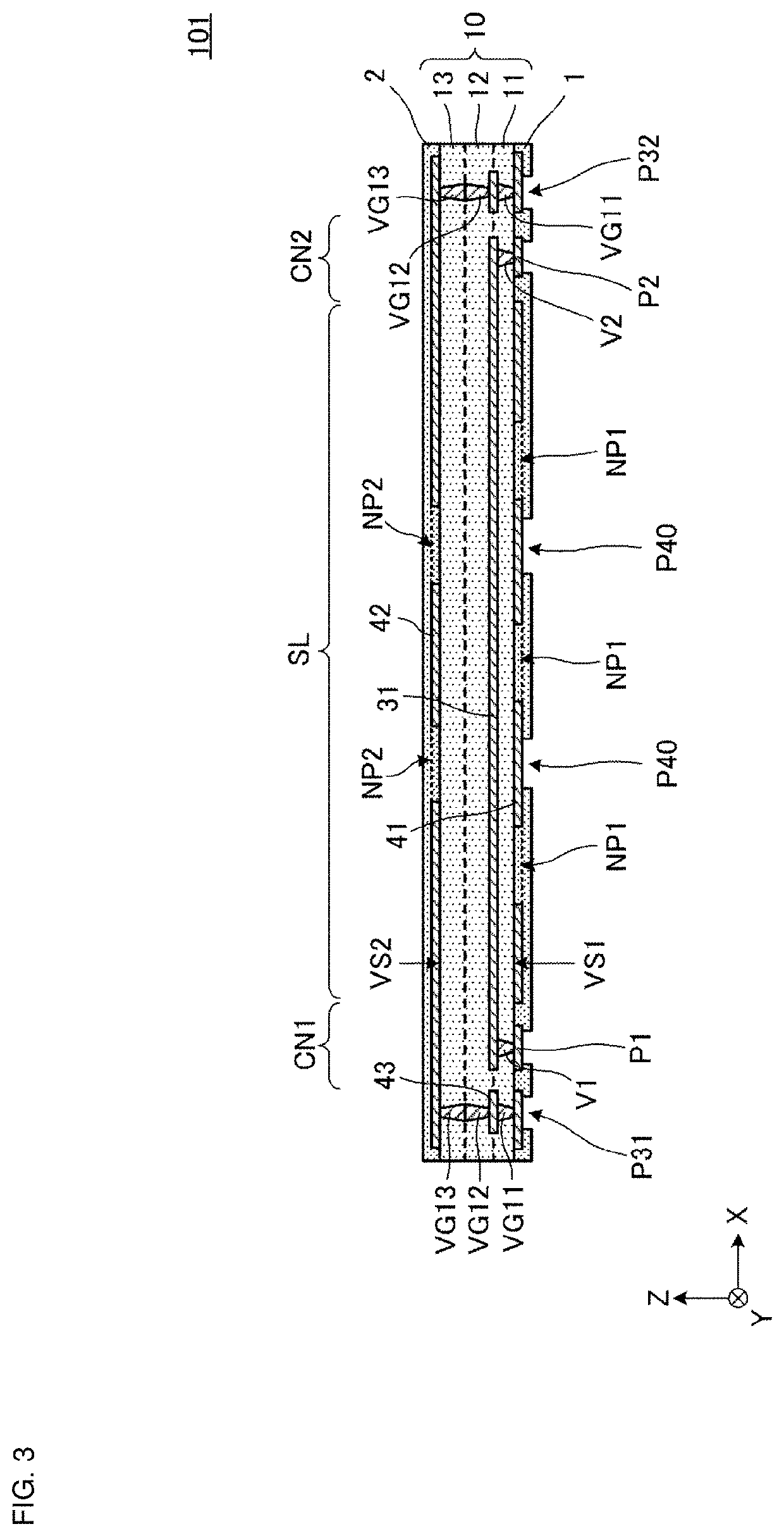
[0027]FIG. 1 is an external perspective view of a transmission line substrate 101 according to a first preferred embodiment of the present invention. FIG. 2 is an exploded plan view of the transmission line substrate 101. FIG. 3 is a cross-sectional view along A-A in FIG. 1. FIG. 4A is a cross-sectional view along B-B in FIG. 1. FIG. 4B is a cross-sectional view along C-C in FIG. 1.

[0028]The transmission line substrate 101 according to the present preferred embodiment is, for example, a cable which connects electronic components, which are mounted on a single circuit substrate, or connects circuit substrates to each other.

[0029]The transmission line substrate 101 includes connection portions CN1 and CN2 and a line portion SL. The connection portions CN1 and CN2 are portions connected to different circuit substrates. As described in detail below, the line portion SL includes a transmission line (strip line) which connects the connection portions CN1 and CN2 to each other. In the tran...

second preferred embodiment

[0072]A second preferred embodiment of the present invention describes an exemplary transmission line substrate in which conductor-non-formed portions are not disposed in the second ground conductor.

[0073]FIG. 6 is an external perspective view of a transmission line substrate 102 according to the second preferred embodiment. FIG. 7 is an exploded plan view of the transmission line substrate 102.

[0074]The transmission line substrate 102 is different from the transmission line substrate 101 according to the first preferred embodiment in that a second ground conductor 42A, which is solid and in which conductor-non-formed portions are not disposed, is included. The remaining configuration of the transmission line substrate 102 is the same or substantially the same as that of the transmission line substrate 101.

[0075]In the transmission line substrate 102 according to the present preferred embodiment, the second ground conductor 42A is a solid conductor pattern. This configuration improv...

third preferred embodiment

[0076]A third preferred embodiment of the present invention describes an exemplary transmission line substrate including multiple signal lines.

[0077]FIG. 8A is an external perspective view of a transmission line substrate 103 according to the third preferred embodiment. FIG. 8B is a cross-sectional view along D-D in FIG. 8A.

[0078]The transmission line substrate 103 is different from the transmission line substrate 101 according to the first preferred embodiment in that a base 10A, input / output electrodes P11, P12, P13, P14, P21, P22, P23, and P24, multiple signal lines 31, 32, 33, and 34, a first ground conductor 41A, the second ground conductor 42A, four auxiliary electrodes P41, multiple interlayer connection conductors VG21, multiple interlayer connection conductors VG22, and multiple interlayer connection conductors VG23 are included. The remaining configuration of the transmission line substrate 103 is the same or substantially the same as that of the transmission line substrat...


PUM

PropertyMeasurementUnit
Timeaaaaaaaaaa
Widthaaaaaaaaaa
Areaaaaaaaaaaa

Abstract

A transmission line substrate includes a line portion, a base including a first main surface and a second main surface opposite to the first main surface, first and second ground conductors, and a signal line. The first ground conductor is on the first main surface side. The second ground conductor is on the second main surface side. The first ground conductor includes first conductor-non-formed portions overlapping the signal line when viewed in the Z axis direction. The second ground conductor includes second conductor-non-formed portions overlapping the signal line when viewed in the Z axis direction. A total area of the second conductor-non-formed portions is less than a total area of the first conductor-non-formed portions.

Description

CROSS REFERENCE TO RELATED APPLICATIONS[0001]This application claims the benefit of priority to Japanese Patent Application No. 2019-141239 filed on Jul. 31, 2019 and is a Continuation Application of PCT Application No. PCT / JP2020 / 025996 filed on Jul. 2, 2020. The entire contents of each application are hereby incorporated herein by reference.BACKGROUND OF THE INVENTION1. Field of the Invention[0002]The present invention relates to a transmission line substrate, which includes a signal line and two ground conductors sandwiching the signal line in between, and an electronic device including the transmission line substrate.2. Description of the Related Art[0003]In the related art, a known transmission line substrate (flat cable) includes a base and multiple conductor patterns (a signal line, and a first ground conductor and a second ground conductor which sandwich the signal line in between) which are formed in the base.[0004]For example, International Publication No. 2016 / 088592 disc...

Claims


Application Information

Patent Timeline
IPC IPC(8): H01P3/08H01P3/00H05K1/02H05K3/28
CPCH01P3/088H01P3/003H05K2201/0141H05K3/28H05K1/0242H01L23/12H01P3/085H05K1/0218
Inventor OOI, KOSUKEITO, SHINGOKOYAMA, HIROMASAKATO, GENROMISHIMA, KOTARO
Owner MURATA MFG CO LTD
Why Eureka
Try Eureka