

Differential locking mechanism
a locking mechanism and differential technology, applied in the direction of differential gearings, belts/chains/gearrings, differential gearings, etc., can solve the problems of high material requirements, complex structure, and existing differential locking mechanisms, and achieves simple overall structure, convenient operation and use, and good stability
- Summary
- Abstract
- Description
- Claims
- Application Information
AI Technical Summary
Benefits of technology
Problems solved by technology
Method used
Image


Examples
first embodiment
[0012]With reference to FIG. 2, the description taken in conjunction with the embodiments is as follows: a differential locking mechanism includes a differential mechanism and a locking mechanism. The differential mechanism includes a driven gear 1, a shell 2, two half shafts 10, two half-shaft gears 14 and a planetary gear A3, a planetary gear B4, a first planetary gear shaft 5 and a second planetary gear shaft 15; one end of the shell 2 is fixedly provided with the driven gear 1, and each end of the shell 2 is respectively provided with a corresponding half shaft 10 in a rotating way; one end of each of the two half shafts 10, facing inside of the shell 2, is fixedly provided with a corresponding half-shaft gear 14; the planetary gear A3 and the planetary gear B4 are rotationally and symmetrically arranged around the two half-shaft gears 14; the planetary gear B4 is rotationally arranged in the shell 2 through the second planetary gear shaft 15; the second planetary gear shaft 15 ...
second embodiment
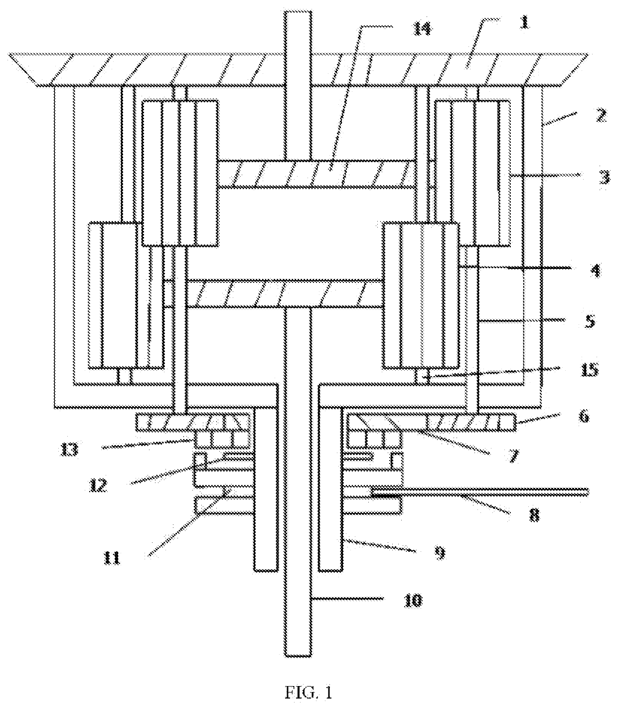
[0016]Referring now to FIG. 1, the description taken in conjunction with the examples is as follows: a differential locking mechanism includes a differential mechanism and a locking mechanism. The differential mechanism includes a driven gear 1, a shell 2, two half shafts 10, two half-shaft gears 14 and a planetary gear A3, a planetary gear B4, a first planetary gear shaft 5 and a second planetary gear shaft 15; one end of the shell 2 is fixedly provided with the driven gear 1, and each end of the shell 2 is respectively provided with a corresponding half shaft 10 in a rotating way; one end of each of the two half shafts 10, facing inside of the shell 2, is fixedly provided with a corresponding half-shaft gear 14; the planetary gear A3 and the planetary gear B4 are rotationally and symmetrically arranged around the two half-shaft gears 14; the planetary gear B4 is rotationally arranged in the shell 2 through the second planetary gear shaft 15; the second planetary gear shaft 15 is p...
PUM
 Abstract
Description
Claims
Application Information