Optical communication apparatus, optical communication method, and optical communication system

a communication apparatus and optical communication technology, applied in the field of optical communication apparatus, optical communication method, optical communication system, can solve the problems of single-mode fiber, increase in cost, and significant loss of optical power of optical communication, so as to reduce the loss of optical power coupling, and relax the effect of accuracy

Pending Publication Date: 2022-03-17
SONY CORP
View PDF2 Cites 0 Cited by
  • Summary
  • Abstract
  • Description
  • Claims
  • Application Information

AI Technical Summary

Benefits of technology

[0014]Thus, when there is a positional deviation, input light that is not headed for the core of the optical waveguide of the reception section from the transmission section is guided to the core of the optical waveguide due to the light path adjuster adjusting a path of the light. Here, the angle of incidence with which transmission can be performed by the optical waveguide, is made larger by using light of the second wavelength, compared to the use of light of the first wavelength. This results in a reduction in a loss of coupling of optical power. Further, propagation is performed by the optical waveguide in at least the first order mode in addition to the reference mode, the at least the first order mode being generated due to the light path adjuster adjusting a path of the input light. This results in a reduction in a loss of coupling of optical power. This makes it possible to relax the accuracy with respect to a positional deviation, and thus to reduce costs.

Problems solved by technology

Due to a positional deviation, the optical communication has significant losses of optical power, in particular, in a single-mode fiber.
This results in an increase in costs.

Method used


Image

  • Optical communication apparatus, optical communication method, and optical communication system
  • Optical communication apparatus, optical communication method, and optical communication system
  • Optical communication apparatus, optical communication method, and optical communication system

Examples


Embodiment Construction

[0043]Embodiments for carrying out the present technology (hereinafter referred to as “embodiments”) will now be described below. Note that the description is made in the following order.

1. Embodiments

2. Modifications

1. Embodiments

[0044][Basic Description of Present Technology]

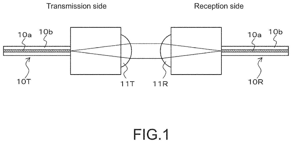
[0045]First, a technology related to the present technology is described. FIG. 1 illustrates an outline of an optical communication performed by spatial coupling. In this case, light exiting an optical fiber 10T on the transmission side is formed into collimated light by a lens 11T on the transmission side, and the collimated light exits the lens 11T. Then, the collimated light is collected by a lens 11R on the reception side, and enters an optical fiber 10R on the reception side. Due to a positional deviation, the optical communication has significant losses of optical power, in particular, in a single-mode fiber. Note that the optical fibers 10T and 10R each have a two-layer structure including a core 10a an...


PUM


Abstract

To relax the accuracy with respect to a positional deviation, and thus to reduce costs.
An optical waveguide and a light path adjuster are included, the optical waveguide performing propagation only in a reference mode at a first wavelength, the light path adjuster adjusting a light path such that input light is guided to a core of the optical waveguide. Communication is performed using light of a second wavelength that enables the optical waveguide to perform propagation in at least a first order mode in addition to the reference mode. When there is a positional deviation, input light that is not headed for the core of the optical waveguide is guided to the core due to the light path adjuster adjusting a path of the light. This results in a reduction in a loss of coupling of optical power. Further, propagation is performed by the optical waveguide in at least the first order mode in addition to the reference mode, the at least the first order mode being generated due to the light path adjuster adjusting a path of the input light. This results in a reduction in a loss of coupling of optical power. This makes it possible to relax the accuracy with respect to a positional deviation, and thus to reduce costs.

Description

TECHNICAL FIELD[0001]The present technology relates to an optical communication apparatus, an optical communication method, and an optical communication system. In particular, the present technology relates to, for example, an optical communication apparatus that makes it possible to relax the accuracy with respect to a positional deviation.BACKGROUND ART[0002]An optical communication performed by spatial coupling (for example, refer to Patent Literature 1) has been known in the past. Due to a positional deviation, the optical communication has significant losses of optical power, in particular, in a single-mode fiber. This makes great demands for the accuracy of a component in order to prevent a positional deviation. This results in an increase in costs.CITATION LISTPatent Literature[0003]Patent Literature 1: WO2017 / 056889DISCLOSURE OF INVENTIONTechnical Problem[0004]An object of the present technology is to relax the accuracy with respect to a positional deviation, and thus to red...

Claims


Application Information

Patent Timeline
Patent Type & Authority Applications(United States)
IPC IPC(8): G02B6/42H04J14/04H04B10/25
CPCG02B6/4215H04J14/04G02B6/4292H04B10/25G02B6/4214G02B6/32G02B6/403
Inventor MORITA, HIROSHITOBA, KAZUAKIYAMAMOTO, MASANORIOYAMA, YUSUKE
Owner SONY CORP
Why Eureka
Try Eureka