
Detection system

a detection system and detection system technology, applied in the direction of mechanical vibration separation, solid separation, sorting, etc., can solve the problems of increasing the dead surface of the screening module, reducing the number of supporting points to a minimum, and not being a convenient alternative,

Active Publication Date: 2022-03-24
METSO SWEDEN AB
View PDF10 Cites 0 Cited by
  • Summary
  • Abstract
  • Description
  • Claims
  • Application Information

AI Technical Summary

Benefits of technology

The invention relates to a detection system for screening devices. The system uses ultrasound sensors to monitor the material leaving the screening device. This allows for the identification of any foreign objects that may have become detached from the screening device. The detection system can detect when screening modules, liner elements, or similar become detached and prevent them from causing further damage or interference. The use of ultrasound sensors allows for flexibility and adjustability in detecting detached screen modules, and can prevent vibrations from affecting the sensor's accuracy. The detection system may be a separate structure from the screening device to protect the sensor from adverse conditions.

Problems solved by technology

This since a screening module of lower strength requires supporting sections arranged at shorter intervals, which results in an increased amount of dead surface of the screening module.
Nevertheless, making the entire screening surface consist of a single screening module and reducing the number of supporting points to a minimum does not constitute a convenient alternative.
Such a method would certainly provide a maximum amount of active surface, but at the price of very high operating expenses since it would be necessary to exchange the entire screen deck also in case of local wear.
A problem with these types of screens is that there is always a risk of the screening modules detaching from the screen panel support during use.
Otherwise, quality of the screened product will become compromised and it is also conceivable that a detached screening element may cause breakdown of the screening device or other apparatuses downstream the screening device.
Further, liner elements used in the screening device may also detach and cause problems downstream the screening device.

Method used


Image

  • Detection system
  • Detection system
  • Detection system

Examples


Embodiment Construction

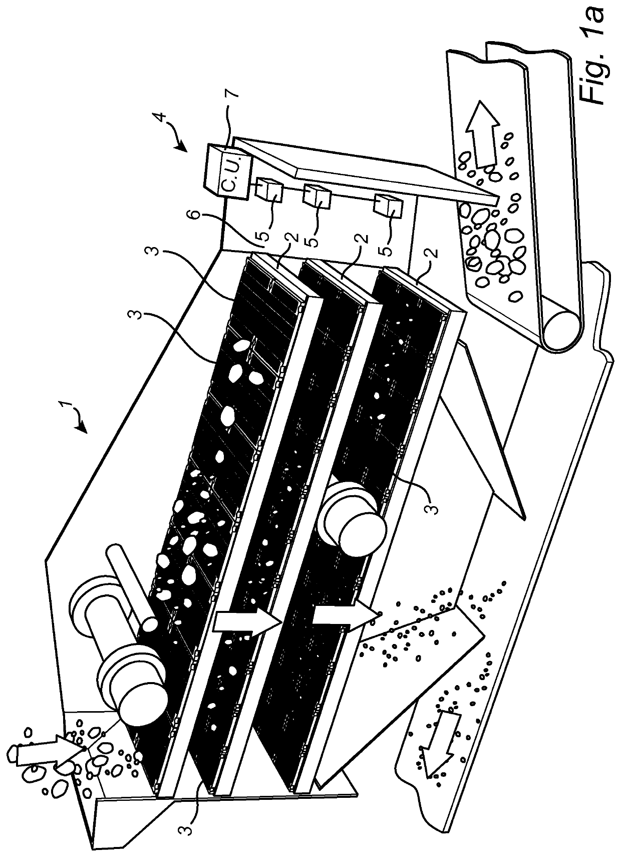
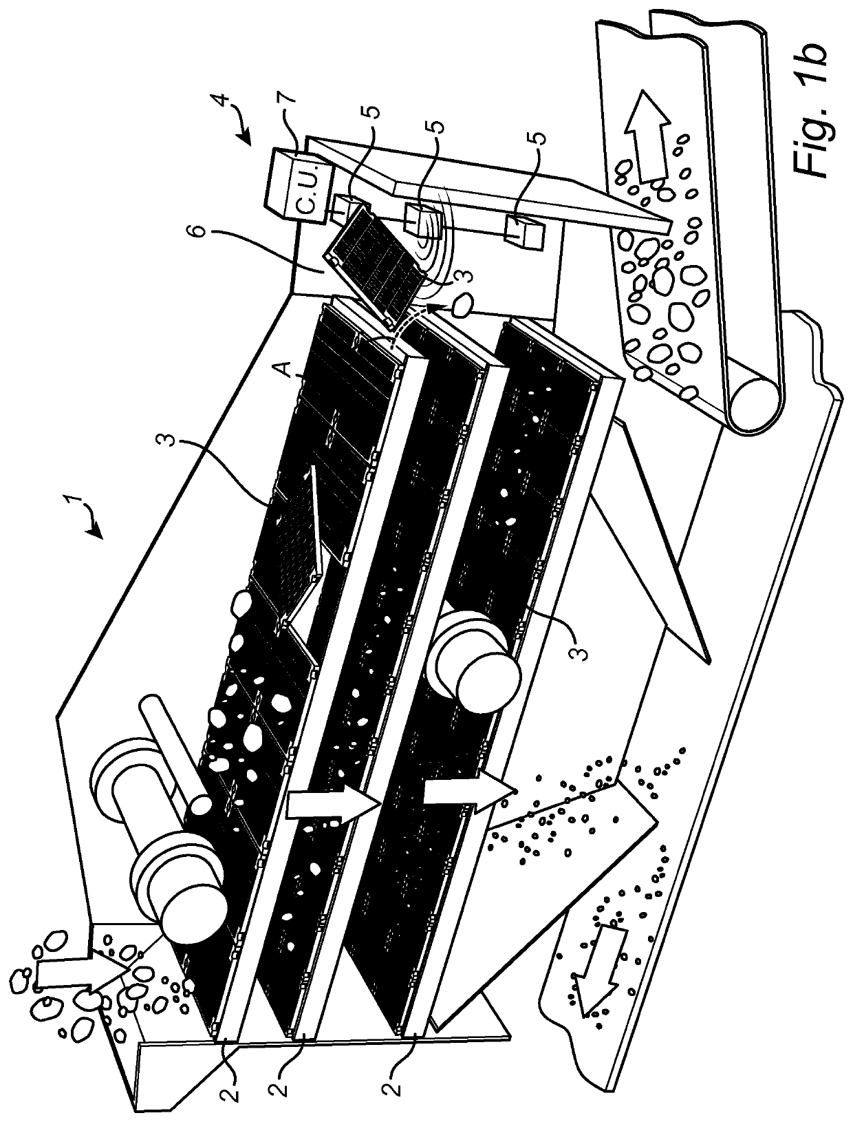
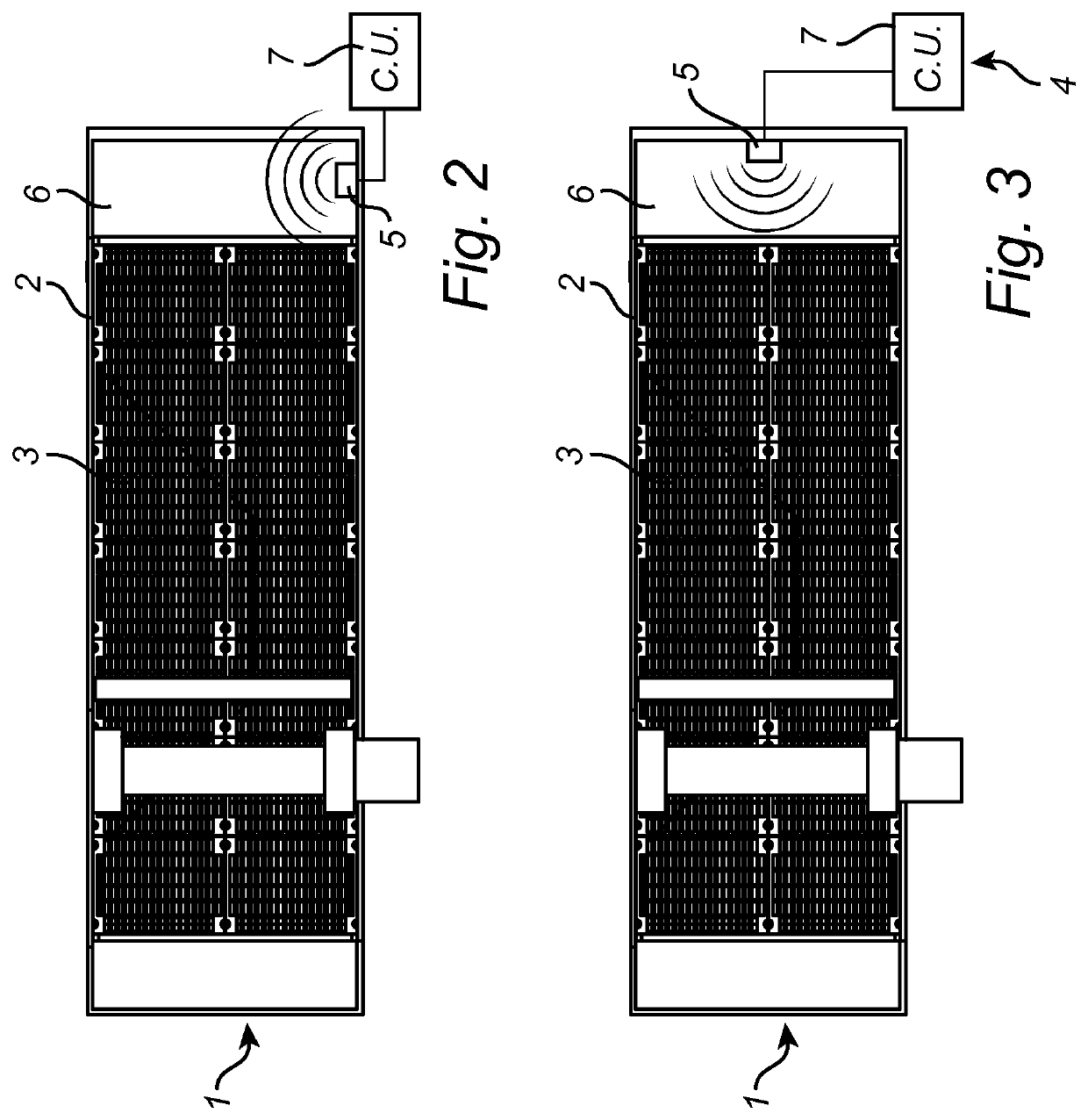
[0041]FIGS. 1a, 1b and 4 illustrate a screening device 1 comprising three screening decks 2, each of which consists of a plurality of screening modules 3. Each screening module 3 has one apertured section. The apertured section has a first, upper surface intended to receive and carry material to be screened, a second, lower surface opposite the first surface, and a circumferential surface. The apertures extend from the first surface to the second surface. The screening device 1 is equipped with a detection system 4 which here comprises three sensors 5. The sensors 5, which, according to the example embodiment, are rangefinders of ultrasound type, are arranged such that they can detect objects present near a discharge 6 of the respective screening deck 2. In this embodiment (see also FIG. 2), each sensor 5 is attached to a side wall arranged downstream of the screening decks 2. The sensors 5 are connected to a control unit 7 and arranged to transmit signals in a direction generally p...


PUM

PropertyMeasurementUnit
strengthaaaaaaaaaa
sizeaaaaaaaaaa
mass flowaaaaaaaaaa

Abstract

The invention relates to a detection system in a screening device for screening material, e.g. aggregate, ore or similar, comprising at least one screening decks, the at least one screening deck having a screening surface comprising one or more screening modules. The system comprises a sensor arranged at or near at least one screening deck of the screening device. The sensor is arranged such that it can detect objects present leaving the at least one screening deck. The invention also relates to a method for detection of objects in a screening device, and use of the detection system.

Description

TECHNICAL FIELD[0001]The invention relates to a detection system and a method for detection of objects in a screening device.BACKGROUND ART[0002]Modern screening devices used for screening of media normally comprise a screen panel support and screening modules which are arranged in the screen panel support. These screens have several advantages compared with those of earlier generations since individual screening modules can be exchanged when worn out or broken.[0003]The screening modules should have an active surface that is as large as possible and the size of the active surface is normally limited by the rigidity of the screening module. This since a screening module of lower strength requires supporting sections arranged at shorter intervals, which results in an increased amount of dead surface of the screening module. Nevertheless, making the entire screening surface consist of a single screening module and reducing the number of supporting points to a minimum does not constitu...

Claims


Application Information

Patent Timeline
Patent Type & Authority Applications(United States)
IPC IPC(8): B07B1/42B06B1/16B07C1/00B07C5/34B07C5/36
CPCB07B1/42B06B1/16B07C5/36B07C5/34B07C1/00B07C5/00
Inventor LARSSON, CLAES
Owner METSO SWEDEN AB
Learn More