
Engraving machine

a laser engraving machine and engraving frame technology, applied in the direction of soldering apparatus, manufacturing tools, auxillary welding devices, etc., can solve the problem of adding complexity to the programming process, and achieve the effect of reducing or eliminating the use of steel and adding rigidity to the frame of the laser housing

Active Publication Date: 2022-03-24
LI TONG
View PDF5 Cites 0 Cited by
  • Summary
  • Abstract
  • Description
  • Claims
  • Application Information

AI Technical Summary

Benefits of technology

The solution enhances structural rigidity, reduces material costs, and significantly improves image resolution and accuracy by minimizing vibration during the engraving process.

Problems solved by technology

This of course adds complexity to the programming process but that technology is within the skill in the art.

Method used


Image

  • Engraving machine
  • Engraving machine
  • Engraving machine

Examples


Embodiment Construction

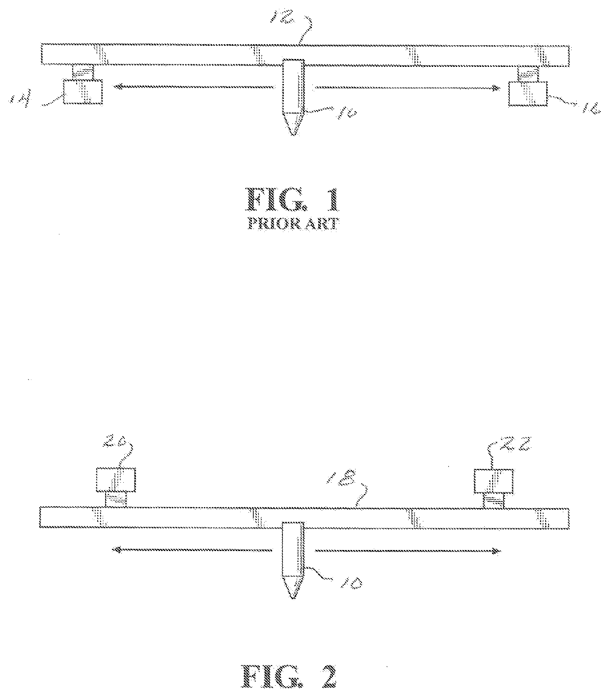
[0012]Reviewing, the prior art X and Y beam structure diagrammatically shown in FIG. 1, it should be noted that the X-axis support beam 12 is mounted over the widely spaced Y-axis support beams 12 and 14 to allow the laser tool 10 to realize maximum translation scope in the positive and negative X-axis direction.

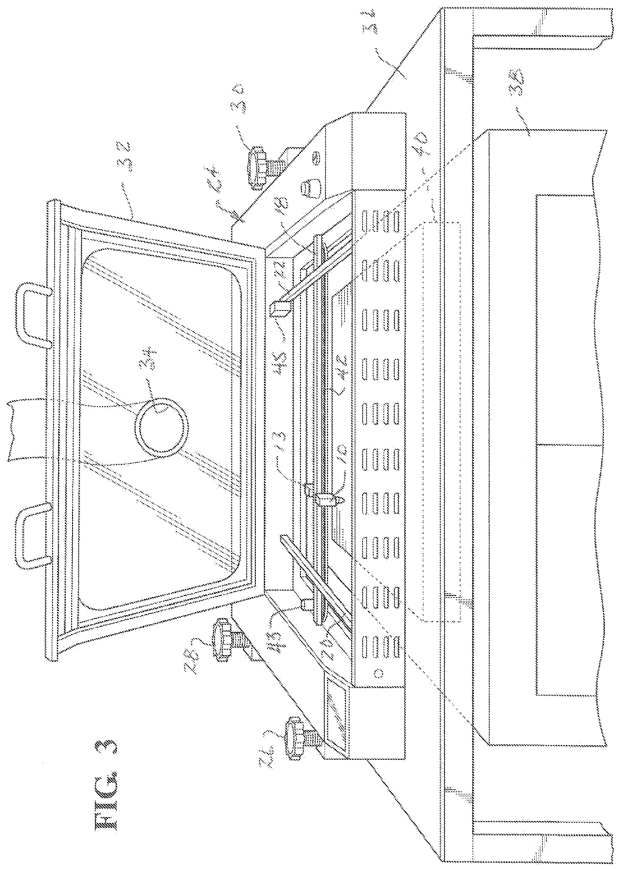
[0013]FIG. 2 on the other hand, shows the new arrangement in which the laser tool 10 and the X-axis support structure 18 is mounted to and below the Y-axis support beams 20 and 22 thereby allowing those beam structures to be moved closer together, adding substantial additional rigidity to the housing 24 shown in FIGS. 3 and 4.

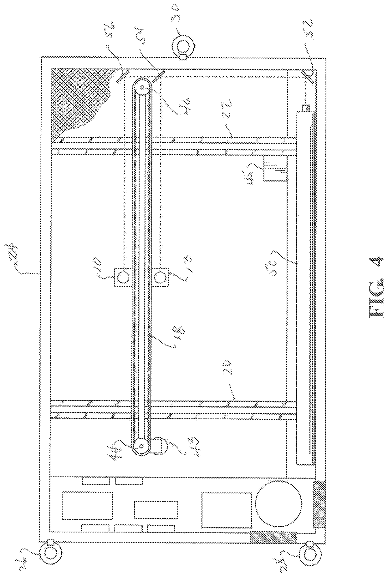
[0014]Referring to FIGS. 3 and 4, the laser machine 24 is shown to comprise a box-like metal housing with an interior volume adapted to contain the X-axis support structure 18 for the downwardly-aimed laser engraving tool 10 which is moveable along the X-axis by means of a belt 42 mounted on pulleys 44 and 46 driven by a stepper motor 43 as disclosed in...


PUM

PropertyMeasurementUnit
massaaaaaaaaaa
structural strengthaaaaaaaaaa
focal distanceaaaaaaaaaa

Abstract

A laser engraving machine with a three-point suspension system and an inverted X-Y axis support system wherein the X-axis beam is to and mounted below the Y-axis beams and the Y-axis beams are mounted inwardly of the outer ends of the X-axis beam and are structurally integrated with the machine housing. In addition, a counterweight in the form of a second, independently activatable laser is added to the drive belt to reduce or eliminate vibration during rapid reciprocal movement of the tool during an engraving process.

Description

CROSS-REFERENCE TO RELATED APPLICATIONS[0001]This application is a divisional application of U.S. patent application Ser. No. 16 / 987,529, filed Aug. 7, 2020 which claims priority to U.S. Provisional Patent Application Ser. No. 62 / 986,056, filed on Mar. 6, 2020, the entire disclosures of which are incorporated by reference.FIELD OF THE INVENTION[0002]This document describes an improved laser engraving machine for engraving objects made of various materials including stone, metal wood and plastic with letters, numbers, images and combinations thereof, and more particularly to an engraving machine having a novel arrangement of X and Y axis tool support and guidance structures to provide improved structural strength, thereby allowing for the use of lighter materials of construction. The disclosure further describes a device having a counter-weighted X-axis laser drive, which substantially eliminates vibration and loss of image resolution in the engraving process.BACKGROUND OF THE INVENT...

Claims


Application Information

Patent Timeline
Patent Type & Authority Applications(United States)
IPC IPC(8): B23K26/08B23K26/364B23K26/70
CPCB23K26/0876B23K26/702B23K26/364B23K26/362B23K26/0869B23K26/083B23K26/02B23K26/16B23K26/06B23K26/0604B23K26/40B23K37/0235B23K37/0408B23K26/127
Inventor LI, TONG
Owner LI TONG
Learn More