Recessable box for housing hydraulic components

Inactive Publication Date: 2022-03-31
RBM IBOX SRL
View PDF6 Cites 0 Cited by
  • Summary
  • Abstract
  • Description
  • Claims
  • Application Information

AI Technical Summary

Benefits of technology

[0012]Preferably, the frame is made from a folded sheet metal strip and is

Problems solved by technology

This type of box is generally used for installations in solid walls, where the cavity is obtained through local demolition of the wall itself and it is not possible or practical to control dimensions in a precise manner.
Th

Method used


Image

  • Recessable box for housing hydraulic components
  • Recessable box for housing hydraulic components
  • Recessable box for housing hydraulic components

Examples


Example

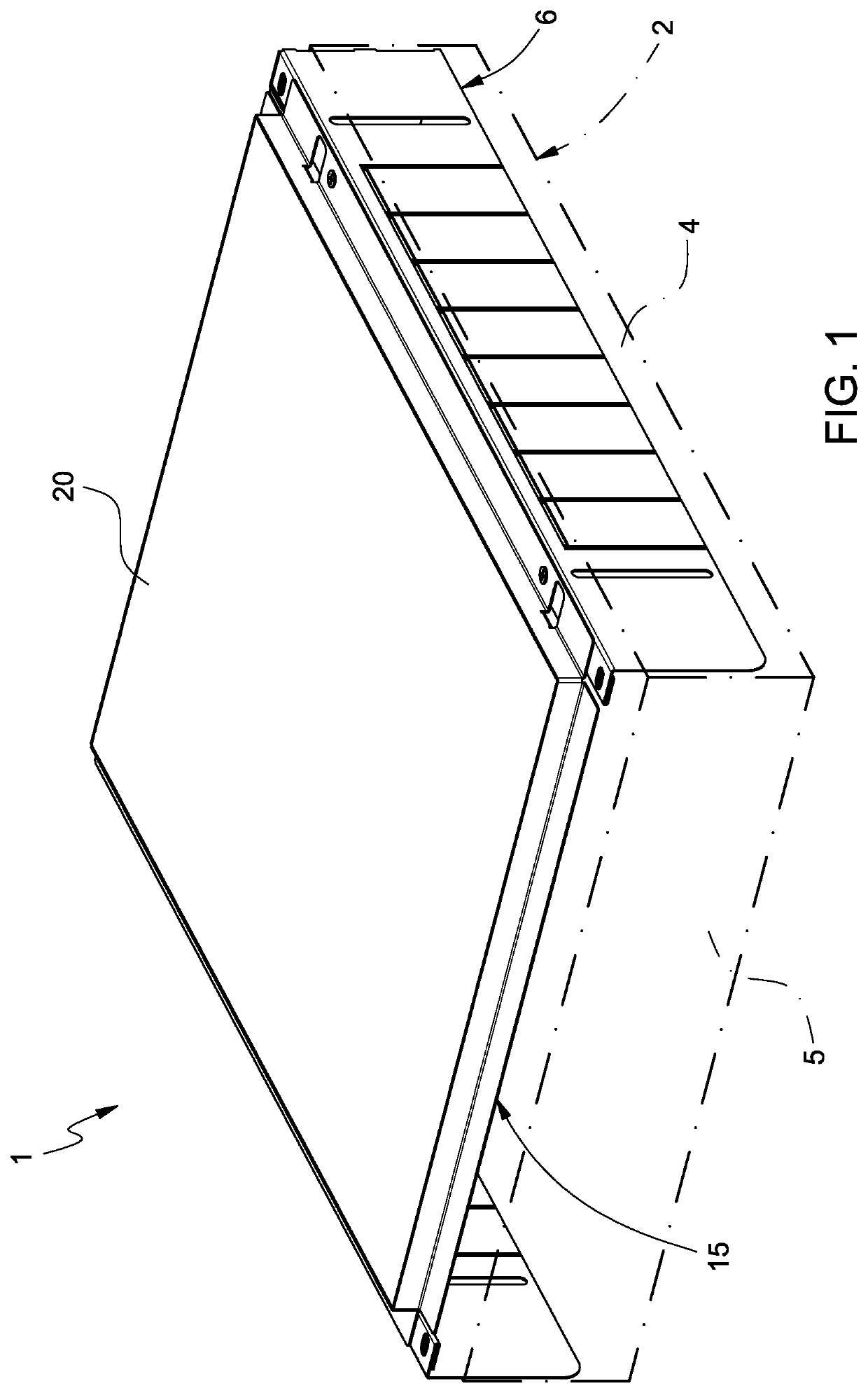
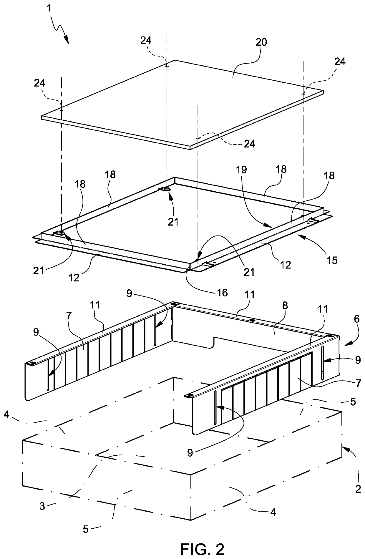
[0020]With reference to FIGS. 1 and 2, number 1 indicates, as a whole, a recessable box for housing hydraulic components according to the invention.

[0021]The box 1 comprises a box-shaped body 2 with a parallelepiped-like shape, which is open at the front and comprises a rectangular bottom wall 3, two longitudinal lateral walls 4 and two transverse lateral walls 5 extending perpendicularly to the bottom wall 3.

[0022]The box 1 further comprises a slide 6 made up of two longitudinal walls 7 and a transverse wall 8, which are telescopically coupled to the corresponding lateral walls 4, 5 so that they can slide relative to them in a direction that is perpendicular to the bottom wall 3 (namely, perpendicularly to the wall in which the box is recessed), thus changing the overall thickness of the box 1. To this aim, the longitudinal walls 7 of the slide have respective pairs of slits 9, through which respective locking screws (not shown) are mounted in a through manner so as to lock them to...


PUM


Abstract

Flush-mounted box for housing hydraulic components comprising a frontally open box body, which is configured to be housed and fixed in a cavity made in a wall, a slide, which is telescopically coupled to the body with the possibility of sliding in a direction perpendicular to the wall, a frame, which is fixed to the slide and is provided with at least one front closing element that can be fixed to the body, and a front closing plate, which can be housed in a compartment of the frame and is designed to cooperate with stop elements of the frame and to be magnetically connected to them; the position of the slide is adjustable so as to place the front closing plate flush with the wall.

Description

CROSS-REFERENCE TO RELATED APPLICATIONS[0001]This patent application claims priority from Italian patent application no. 102020000022721 filed on Sep. 25, 2020 the entire disclosure of which is incorporated herein by reference.TECHNICAL FIELD[0002]The invention relates to a recessable box for housing hydraulic components, in particular components of a heating or sanitary system, such as manifolds, valves and the like.BACKGROUND ART[0003]Boxes of the aforesaid type are known, which comprise a box-shaped body, which is open at the front and is suited to be housed and fixed in a dedicated cavity obtained in the wall, and a front closing plate. The plate is generally mounted in contact with the wall, so as frontally close the body and adhere to the wall around the cavity. This type of box is generally used for installations in solid walls, where the cavity is obtained through local demolition of the wall itself and it is not possible or practical to control dimensions in a precise manne...

Claims


Application Information

Patent Timeline
IPC IPC(8): F16L5/00
CPCF16L5/00E03C1/021E04F19/08E03B7/095E04F19/086F24D19/0097
Inventor BOSSINI, GUIDO
Owner RBM IBOX SRL
Why Eureka
Try Eureka