Air purification system

a technology air purification chamber, which is applied in the direction of lighting and heating equipment, heating types, separation processes, etc., can solve the problems of affecting the efficiency of air purification system, occupying a large space, and causing health hazards for office staff and other patients, and achieves the effect of high efficiency

Pending Publication Date: 2022-04-07
TIMILON CORP
View PDF0 Cites 1 Cited by
  • Summary
  • Abstract
  • Description
  • Claims
  • Application Information

AI Technical Summary

Benefits of technology

[0007]According to one embodiment of the present invention there is provided air purifying apparatus comprising a housing, a blower and filter media contained within the housing. The housing comprises at least first and second air inlets and at least one air outlet. The blower is operable to induce a flow of air within the housing. The flow of air is selectively directed along either a first flow path located between the first air inlet and the at least one air outlet or a second flow path located between the second air inlet and the at least one air outlet. The filter media is contained within the housing and positioned across the flow paths, such that the flow of air within the housing passes through the filter media. The filter media comprises an adsorbent, absorbent, and/or neutralizing material capable of removing one or more undesirable substances from the flow of air.
[0008]According to another embodiment of the present invention there is provided air purifying apparatus comprising a housing having first and second air inlets and at least one air outlet, a blower operable to induce a flow of air within the housing, an air diverter assembly, and filter media. The first air inlet is configured to generally draw air into the housing from an enclosed space in which the apparatus is located. The second air inlet is coupled with an elongate duct having a duct inlet and a duct outlet. The duct inlet is configured to be selectively positioned adjacent a localized region within the enclosed space and draw air into the duct from the localized region. The duct outlet is connected to the second air inlet. The blower is operable to induce a flow of air within the housing between either a first flow path located between the first air inlet and the at least one air outlet or a second flow path located betwe

Problems solved by technology

These bacteria and viruses, once liberated from the patient's body, can linger in the procedure room for hours or days and create hazards for office staff and other patients.
In particular, these devices are bulky and occupy quite a bit of space in an operatory that is already filled with equipment.
Many of these systems also do not have the functionality of being a “whole room” air pur

Method used


Image

  • Air purification system
  • Air purification system
  • Air purification system

Examples


Embodiment Construction

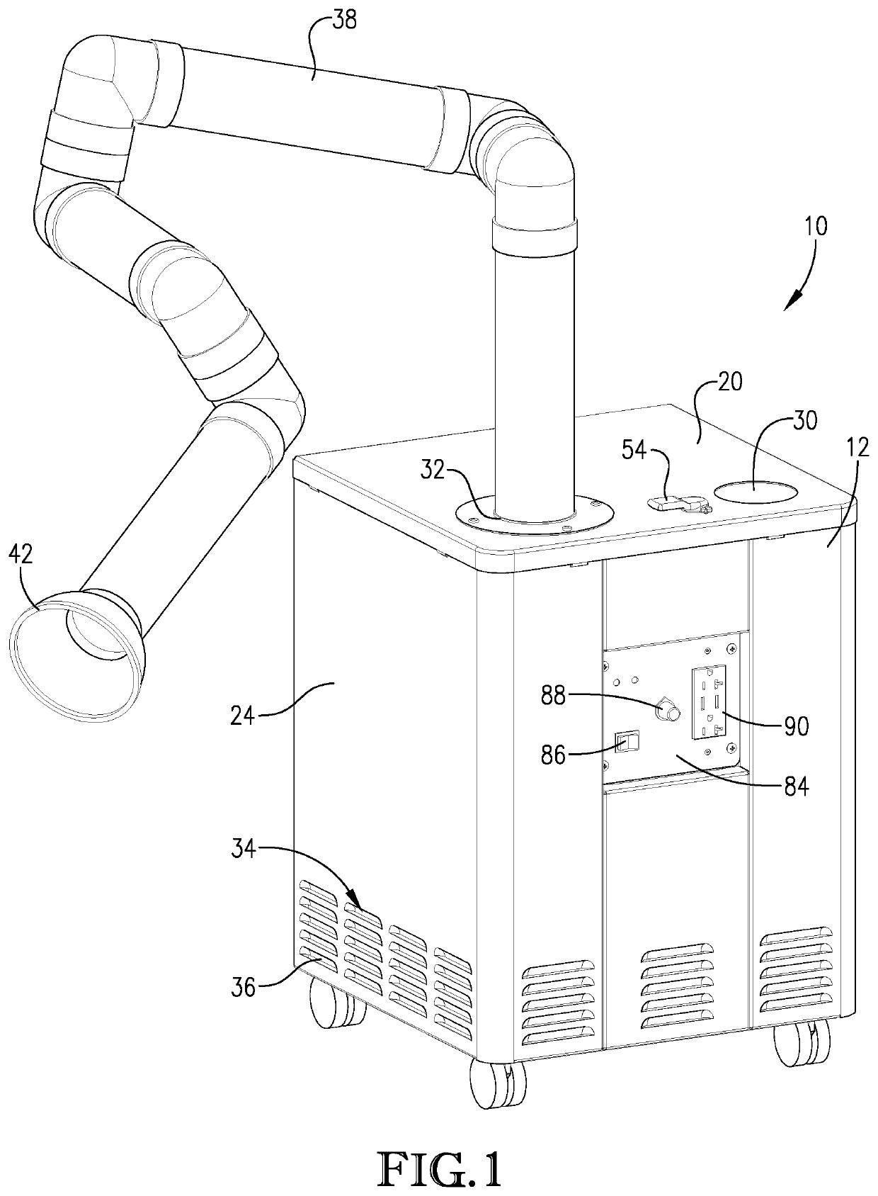
[0022]Turning to FIG. 1, an air purification apparatus 10 in accordance with an embodiment of the present invention is illustrated. Apparatus 10 generally comprises a housing 12 inside of which is contained filter media 14, 16 and a blower 18 (see, FIG. 7) that is operable to induce a flow of air within the housing.

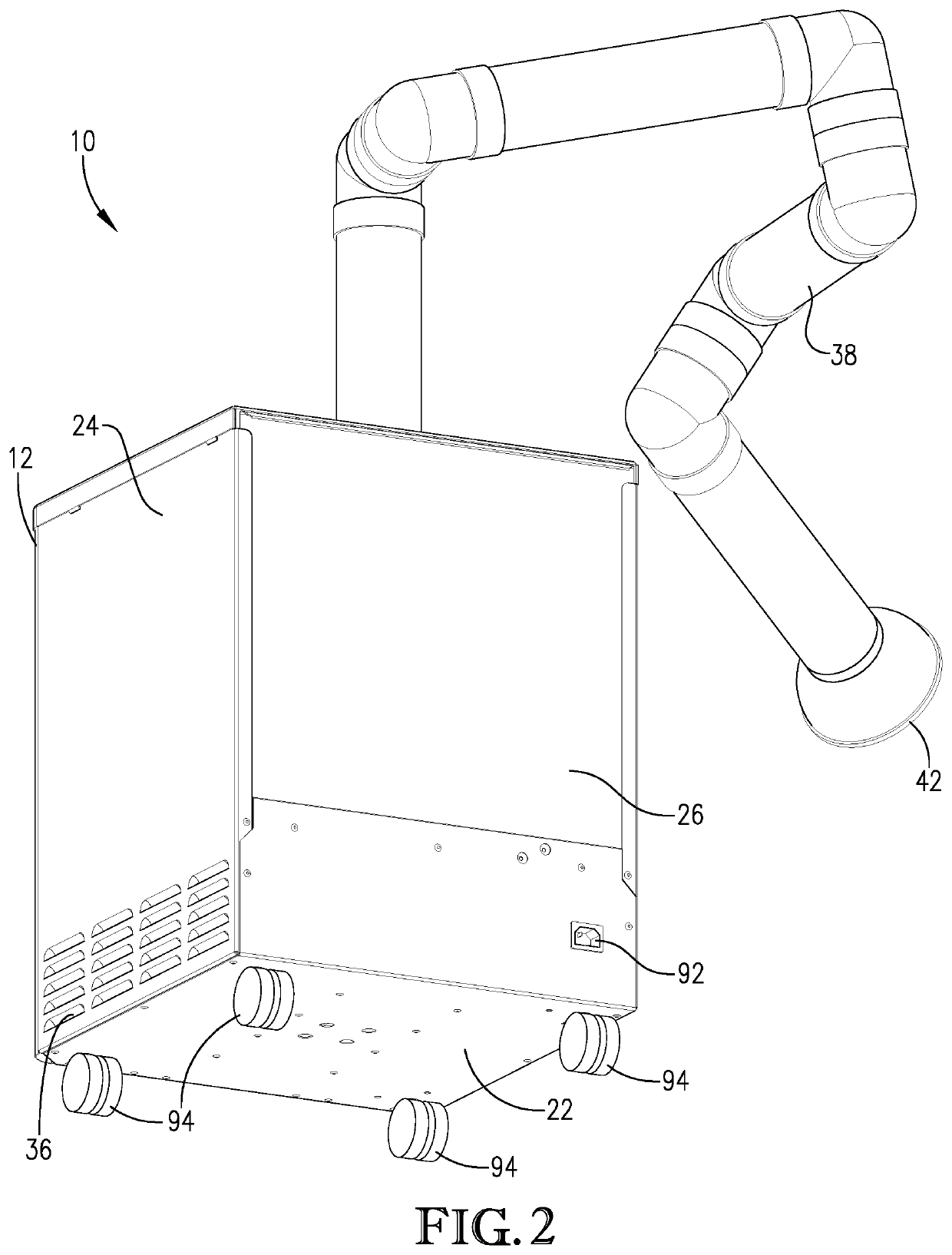
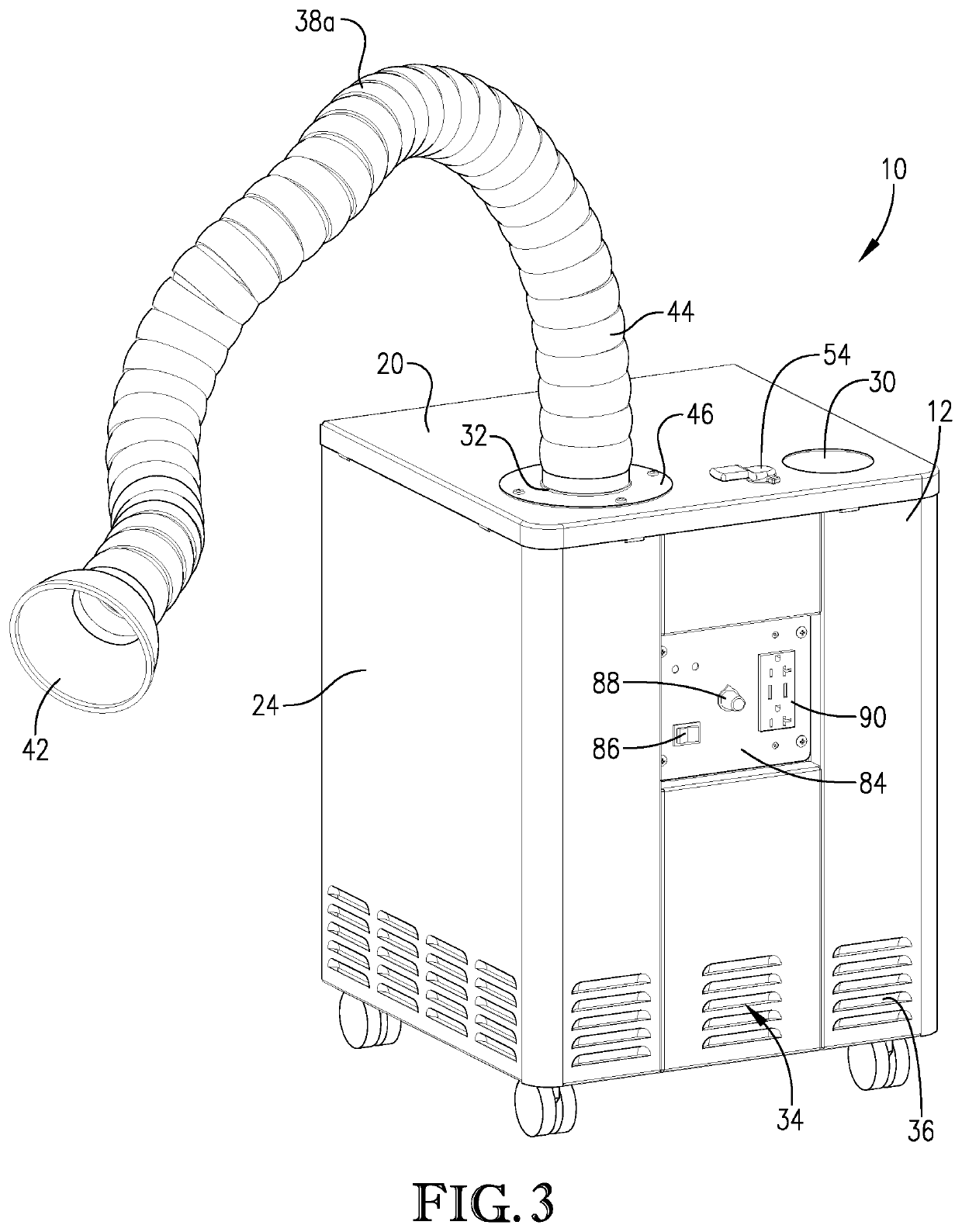
[0023]In one or more embodiments, the housing 10 comprises a top wall 20, a bottom wall 22, and sidewall structure 24. Note, sidewall structure 24 may be comprised of a plurality of individual panels, some of which (e.g., panel 26) may be detachable to expose an interior space 28 within housing 12 within which filter media 14, 16 are located. The housing 12 comprises at least first and second air inlets 30, 32, which may be formed in top wall 20, although this need not always be the case. Note, housing 12 can be configured with a plurality of air inlets (e.g., three, four, five, or more) depending upon the application for apparatus 10. The housing 12 further comprises at ...


PUM

PropertyMeasurementUnit
Fractionaaaaaaaaaa
Fractionaaaaaaaaaa
Massaaaaaaaaaa

Abstract

Air purification apparatus is provided that removes undesirable substances, such as particulate materials, malodors, viruses, bacteria, fungi, and toxins, from the air present within an enclosed environment. The apparatus is switchable between a mode in which air immediately adjacent the apparatus housing is drawn in and purified, and a mode in which air remote from the apparatus housing is drawn in from a specific point within the enclosed environment through use of an elongate duct.

Description

CROSS-REFERENCE TO RELATED APPLICATION[0001]This application claims the benefit of U.S. Provisional Patent Application No. 63 / 086,437, filed Oct. 1, 2020, which is incorporated by reference herein in its entirety.BACKGROUND OF THE INVENTIONField of the Invention[0002]The present invention generally pertains to air purification apparatus that removes undesirable substances, such as particulate materials, malodors, viruses, bacteria, fungi, and toxins, from the air present within an enclosed environment. The apparatus has the capability to draw in and process air from the enclosed environment generally as well as to draw in air from a specific localized space within the enclosed environment.Description of the Prior Art[0003]Aerosols comprising pathogenic and / or toxic materials can be generated by many kinds of processes. Certain medical and dental procedures are well known for generating aerosols that may contain harmful pathogens. In the particular context of dental procedures, the c...

Claims


Application Information

Patent Timeline
IPC IPC(8): B01D46/10F24F8/108B01D46/00B01D39/20
CPCB01D46/10F24F8/108B01D2279/65B01D39/2027B01D2259/804B01D46/0005F24F8/22B01D2239/0258B01D2239/0407B01D39/083B01D39/18B01D39/1615B01D39/1623B01D39/2017B01D39/1676B01D39/1692B01D2239/0485B01D46/521B01D46/12B01D46/0038
Inventor KNAPPENBERGER, KYLEWALKER, BRANDONNEGRON, GEORGESANFORD, BILL R.
Owner TIMILON CORP
Why Eureka
Try Eureka