
Non-mechanical ported perforating torch

a perforating torch and non-mechanical technology, applied in the field of downhole perforating torches, can solve the problems of mud interference with the mechanical moving parts of current thermal perforating torch designs, affecting the mechanical movement of current perforating torch designs, and affecting the operation of perforation or cutting operations

Active Publication Date: 2022-04-07
CHAMMAS PLASMA CUTTERS LLC
View PDF15 Cites 2 Cited by
  • Summary
  • Abstract
  • Description
  • Claims
  • Application Information

AI Technical Summary

Benefits of technology

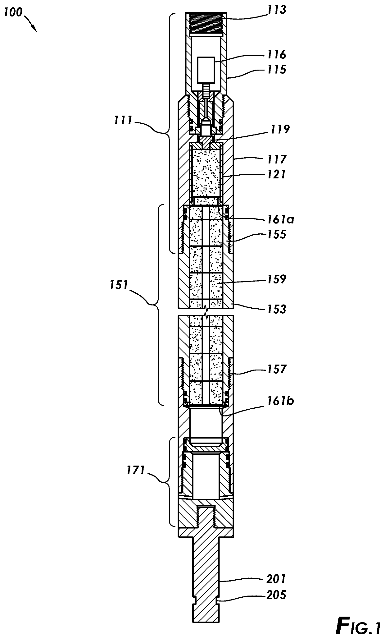
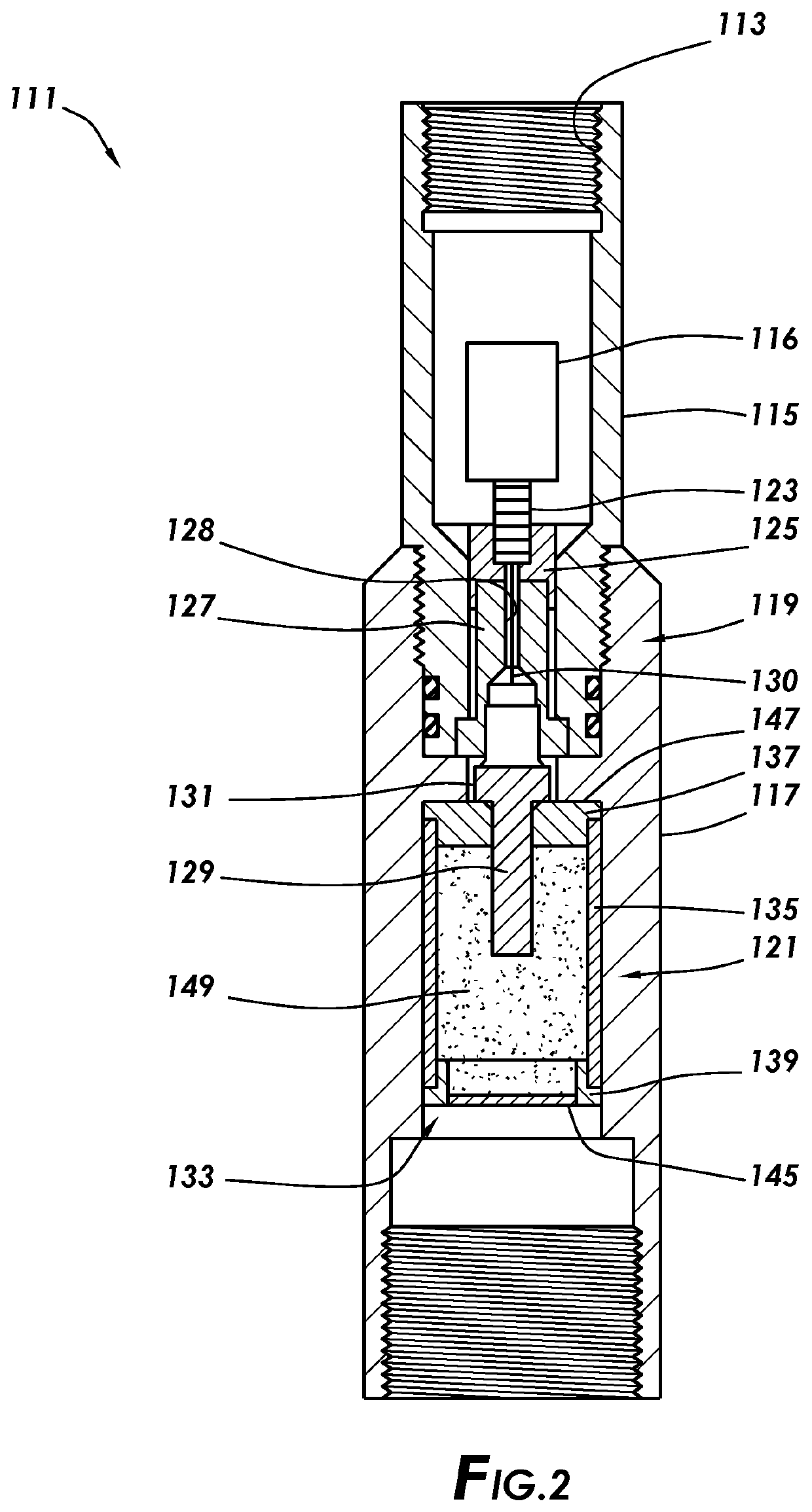
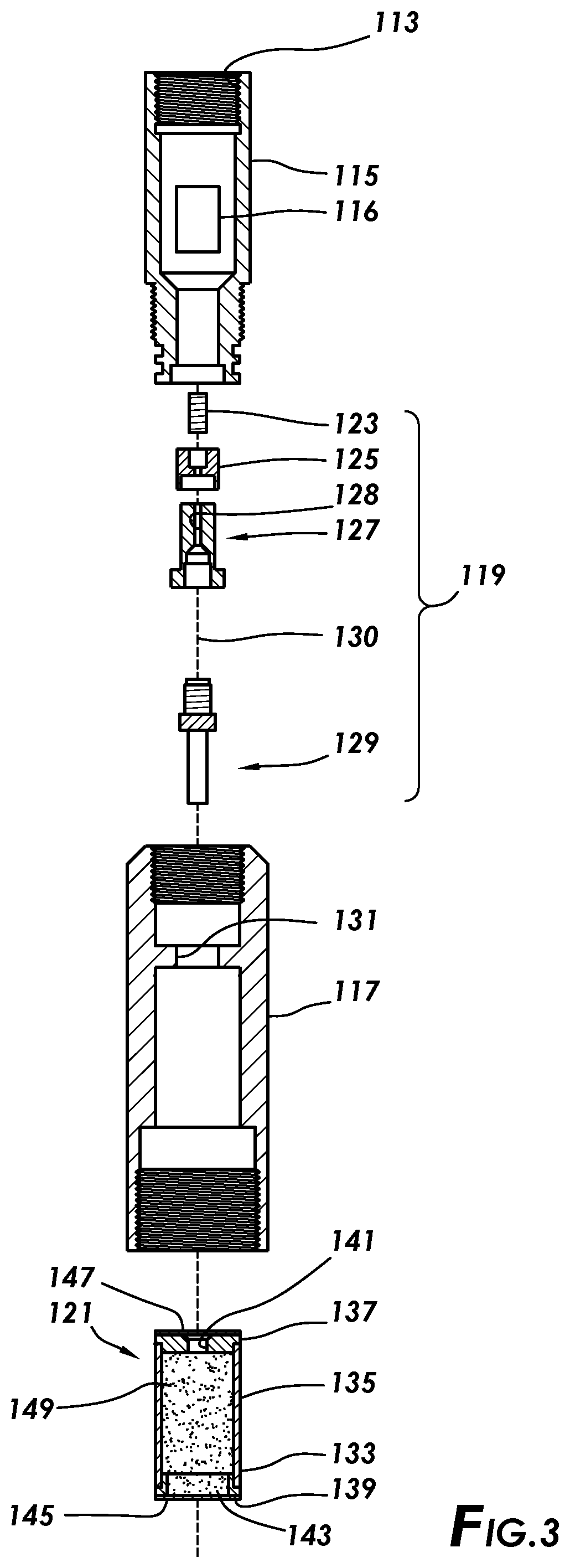
The present invention provides a perforating torch with a thermal igniter assembly and a compressed grain magazine. It also has a perforating head assembly with a port. The technical effect of this invention is a more efficient and effective perforating torch for use in oil and gas drilling operations.

Problems solved by technology

When drilling a subterranean wellbore for the purpose of obtaining petroleum, natural gas, water, and other underground resources, it is sometimes necessary to cut and retrieve pipe or casing during drilling and production operations when unwanted circumstances occur.
However, perforation or cutting operations may swell, crack, or otherwise deform the pipe.
Explosive cutters may also leave debris in the wellbore after the cut, which may cause difficulties with pipe retrieval.
The drilling mud may interfere with mechanical moving parts of current thermal perforating torch designs.

Method used


Image

  • Non-mechanical ported perforating torch
  • Non-mechanical ported perforating torch
  • Non-mechanical ported perforating torch

Examples


Embodiment Construction

[0028]It is to be understood that the following disclosure provides many different embodiments, or examples, for implementing different features of various embodiments. Specific examples of components and arrangements are described below to simplify the present disclosure. These are, of course, merely examples and are not intended to be limiting. In addition, the present disclosure may repeat reference numerals and / or letters in the various examples. This repetition is for the purpose of simplicity and clarity and does not in itself dictate a relationship between the various embodiments and / or configurations discussed.

[0029]For the purposes of the present disclosure, the terms “upper,”“upward,” and “above” refer to the relative direction as within a wellbore in a direction toward the surface regardless of the orientation of the wellbore. For the purposes of this disclosure, the terms “lower,”“downward,” and “below” refer to the relative direction as within a wellbore in a direction ...


PUM


Abstract

A perforating torch includes a thermal igniter assembly, a compressed grain magazine, and a perforating head assembly. The compressed grain magazine is coupled to the thermal igniter. The perforating head assembly includes a port. A port plug may be positioned in the port. A rupture disc may be positioned between the compressed grain magazine and the perforating head.

Description

CROSS-REFERENCE TO RELATED APPLICATIONS[0001]This application is a nonprovisional application which claims priority from U.S. provisional application No. 63 / 087,080, filed Oct. 2, 2020, and U.S. Provisional Application No. 63 / 212,299, filed Jun. 18, 2021, each of which is hereby incorporated by reference herein in its entirety.TECHNICAL FIELD / FIELD OF THE DISCLOSURE[0002]The present disclosure relates generally to downhole tools, and specifically to downhole perforating torches.BACKGROUND OF THE DISCLOSURE[0003]When drilling a subterranean wellbore for the purpose of obtaining petroleum, natural gas, water, and other underground resources, it is sometimes necessary to cut and retrieve pipe or casing during drilling and production operations when unwanted circumstances occur. It is also common to perforate the well casing or production tubing. Some reasons for perforating are concrete squeezes, recirculation of the well, and emptying of fluid from the production tubing during service...

Claims


Application Information

Patent Timeline
Patent Type & Authority Applications(United States)
IPC IPC(8): E21B43/1185E21B43/119E21B34/06
CPCE21B43/1185E21B34/063E21B43/119E21B29/02
Inventor WATKINS, TODD JOSEPHZHANG, JIANCHAMMAS, MICHEL
Owner CHAMMAS PLASMA CUTTERS LLC
Learn More