Burning method and burning device of solid fuel

A solid fuel and combustion device technology, applied in the field of solid fuel combustion methods and combustion devices, can solve the problems of inability to continue combustion, only combustion in an upper combustion chamber, and emission pollution, etc., to achieve orderly and controllable combustion, solve the Safety hazards and the effect of improving combustion efficiency

Inactive Publication Date: 2015-08-05
车战斌
View PDF5 Cites 0 Cited by
  • Summary
  • Abstract
  • Description
  • Claims
  • Application Information

AI Technical Summary

Problems solved by technology

[0008] 1) Low combustion efficiency
During combustion, since the precipitation temperature of volatile components is lower than the ignition point of volatile components, volatile components are first precipitated and discharged into the air in the form of black smoke, and the remaining fixed carbon is burned again, so that only the fixed carbon in it is used for combustion The heat generated not only has relatively low combustion efficiency, but also has emission pollution.
[0009] 2) can not continue to burn
[0012] The hot blast stove test method solves the problems of forward combustion and reverse combustion by combining positive and negative combustion. However, when the hot blast stove 900 is in use, it has the following defects and cannot be used continuously:
[0013] 1) Since the upper combustion chamber 92 and the lower combustion chamber 93 are separated by the upper grate 94, during the combustion process, the incompletely burned fuel in the upper combustion chamber 92 needs to fall into the lower combustion chamber 93 to continue burning. The burning speed of the incompletely burned fuel in the lower combustion chamber 93 cannot match the speed at which the material is dropped into the lower combustion chamber 93 through the upper furnace grate 94, and the incompletely burned fuel piled up in the lower combustion chamber 93 is more and more. Afterwards, the smoke outlet 98 in the lower combus...

Method used


Image

  • Burning method and burning device of solid fuel
  • Burning method and burning device of solid fuel
  • Burning method and burning device of solid fuel

Examples


Embodiment Construction

[0060] The following will clearly and completely describe the technical solutions in the embodiments of the present invention with reference to the accompanying drawings in the embodiments of the present invention. Obviously, the described embodiments are only some, not all, embodiments of the present invention. Based on the embodiments of the present invention, all other embodiments obtained by persons of ordinary skill in the art without creative efforts fall within the protection scope of the present invention.

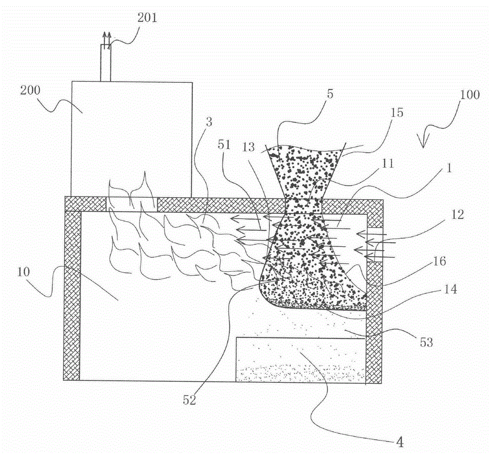
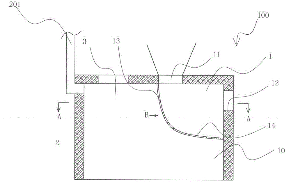
[0061] The invention provides a method for burning solid fuel, such as figure 2 As shown, a solid fuel stockpiling area 1 is provided in the furnace 10 , and a combustion chamber 3 connected to an exhaust gas outlet 201 is provided outside the side wall 13 of the stockpiling area 1 . When burning, the solid fuel 5 enters the stockpile area 1 from the feed port 11 at the top of the stockpile area 1, forms a stockpile layer in the stockpile area 1, ignites in the sto...


PUM


Abstract

The invention provides a burning method and a burning device of a solid fuel. The burning method is to define a stacking area in a hearth; a burning cavity is formed in one side of the stacking area; in burning, the solid fuel enters the stacking area from the top of the stacking area; wind enters from the other side of the stacking area opposite to the burning cavity; the lower layer of the fuel is burnt to generate burning flame; the upper layer of the fuel is heated to separate out a volatile matter; the wind transversely penetrates through the upper layer of the fuel, and carries the separated volatile matter to flow towards the burning cavity; and thermal ignition generated by the volatile matter burning flame is burnt in the burning cavity. The burning method not only can enable the volatile matter to be fully burnt, but also can realize natural matching between the automatic ordered feeding and the burning speed, solves the ash melting problem, and guarantees the stable lasting burning.

Description

technical field [0001] The invention relates to the field of solid fuel combustion, in particular to a solid fuel combustion method and a combustion device. Background technique [0002] From the perspective of fuel classification, solid fuel is the most widely used combustion material for modern humans because of its rich resources and safe use, especially coal. In addition, with the increase of demand for mineral solid fuel represented by coal, the reduction of resources, and the development of the global new energy movement, renewable biomass combustion materials, such as straw, straw, wood, sawdust, Dead branches etc. are highly valued by people. [0003] At present, the main method of using biomass combustion materials is to directly ignite and burn, which has a very low combustion efficiency and produces a large amount of black smoke, causing environmental pollution. [0004] For a long time, many people have tried to use existing coal-fired stoves to burn biomass fu...

Claims


Application Information

Patent Timeline
IPC IPC(8): F23B60/00
Inventor 车战斌
Owner 车战斌
Why Eureka
Try Eureka