Eureka AIR delivers breakthrough ideas for toughest innovation challenges, trusted by R&D personnel around the world.

Fault detection in a three-phase dab converter

Pending Publication Date: 2022-04-14
DEERE & CO
View PDF1 Cites 0 Cited by
  • Summary
  • Abstract
  • Description
  • Claims
  • Application Information

AI Technical Summary

Benefits of technology

The patent describes a method for analyzing the waves of a 3-Φ DAB converter during normal and fault conditions. The researchers identified the main symptoms of the converter during fault modes and found a unique pattern in the DC bias of phase currents. They then developed a logic-based fault diagnosis method to detect the fault and identify the faulty transistor. The technical effect of this patent is to provide a reliable and accurate way to diagnose faults in a 3-Φ DAB converter.

Problems solved by technology

With a DAB converter, an open-circuit fault may occur due to semiconductor device failure or gate drive circuit failure.
Both these failures can stop the switching of the device and lead to an open-circuit fault.
Further, with the adoption of wide-bandgap semiconductor devices, the rate of failure changes with 19% of component failures related to the gate drive and 57% related to the semiconductor device.
However, these studies assume that the fault location is known and do not provide strategies to detect and identify the location of the fault.

Method used


Image

  • Fault detection in a three-phase dab converter
  • Fault detection in a three-phase dab converter
  • Fault detection in a three-phase dab converter

Examples


Embodiment Construction

[0019]Three-Phase DAB: Normal Operation Vs Fault Mode Operation

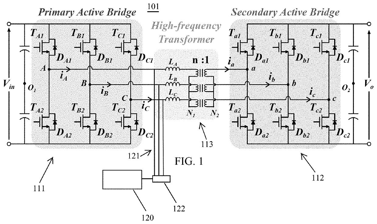
[0020]The topology of three-phase dual active bridge (3-Φ DAB) converter 101 is shown in FIG. 1. It consists of two three-phase active bridges 111 / 112 connected through a transformer-inductor arrangement 113. The input bridge (referred to as primary bridge 111) acts as an inverter and converts the DC input into high-frequency AC. These AC voltages and currents are transformed as per the turns ratio of the high-frequency transformer. The output bridge (referred to as the secondary bridge 112) acts as a rectifier and converts the transformed AC to DC output.

[0021]Normal Operation

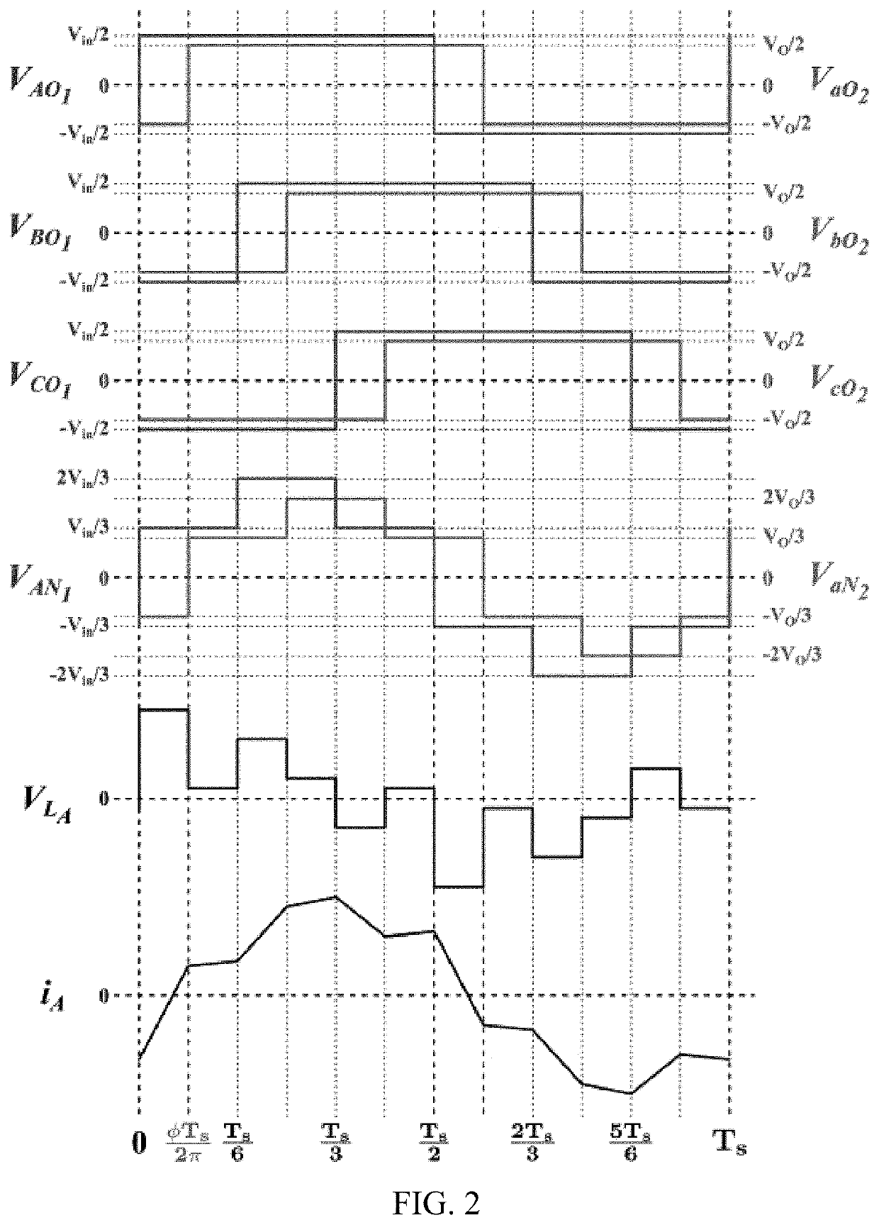
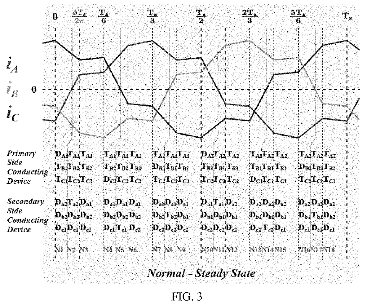
[0022]The 3-Φ DAB 101 is typically operated with 50% duty cycle for each phase-leg ‘χ’ i.e. Tχ1 and Tχ2 are ON for 50% time period (Ts) and are complementary to each other. The gate signals for different phase-legs in a bridge are shifted by 120° with respect to each other. FIG. 2 shows the normal operating AC current waveforms of 3-Φ DAB converter...


PUM


Abstract

A system and method of fault detection based on a detailed waveform analysis is presented for transient and steady-state fault operation of 3-Φ DAB converter. Main symptoms of the converter during normal and fault conditions have been identified and a unique pattern in DC bias of phase currents under fault mode is noted. The logic-based fault diagnosis scheme is used to detect the fault and identify the faulty transistor.

Description

CROSS-REFERENCE TO RELATED APPLICATIONS[0001]This application claims the benefit under 35 U.S.C. § 119 of Provisional Application Ser. No. 63 / 198,284, filed Oct. 8, 2020; Provisional Application Ser. No. 63 / 143,768, filed Jan. 29, 2021; and Provisional Application Ser. No. 63 / 220,884, filed Jul. 12, 2021, each of which is incorporated herein by reference.STATEMENT REGARDING FEDERALLY SPONSORED RESEARCH[0002]This invention was made with U.S. government support under contract or award No. DE-EE0006521 awarded by the Department of Energy. The Government has certain rights in the invention. The award subrecipient, John Deere Electronic Solutions, Inc., of the aforementioned contract or award elects title to any and all subject inventions set forth in this disclosure for U.S. and any European patent filings.BACKGROUND OF THE INVENTION[0003]The present disclosure relates generally to power converters. More specifically, the disclosure relates to a method and system for detecting open-circ...

Claims


Application Information

Patent Timeline
IPC IPC(8): H02M3/335H02M3/155H02M7/49H02M1/32
CPCH02M3/33584H02M1/325H02M7/49H02M3/155H02M1/32
Inventor RASTOGI, SAGAR K.SINGH, BRIJ N.
Owner DEERE & CO
Why Eureka
Eureka Blog
Learn More